Rick's b.log - 2013/07/29
You are 3.142.131.51, pleased to meet you!
Rick's b.log - 2013/07/29 |
|
| It is the 21st of November 2024 You are 3.142.131.51, pleased to meet you! |
|
mailto: blog -at- heyrick -dot- eu
There is an alternative to paying a lot of money for an HD compliant monitor (or TV, assuming the signal processing doesn't interfere). The alternative is a little box that plugs into the HDMI port and "converts" the signal to something that an old-fashioned analogue VGA monitor could work with.
From eBay, the devices are not expensive. This is the one I purchased, which cost €2,99 plus €10,99 postage. As it had the smaller style HDMI plug, I needed an adaptor which cost €2,38 with €1,16 postage (conversion from £).
The HDMI to VGA adaptor uses a fair bit more, I've seen everything from 150mA to 400mA, though I have not measured it myself (and it may depend upon resolution, refresh rate, and whether or not sound is playing). One thing is for certain, it consumes more than the 50mA allocation.
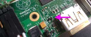
In the case of the Raspberry Pi, a small diode provides power to the HDMI. This diode is capable of supplying enough power to run the Lontium chip that handles the HDMI to VGA conversion, however it gets alarmingly warm and is liable to blow.
Here is the location of the diode in the Raspberry Pi, you don't want to blow this up! :
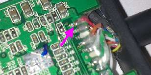
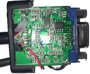
We will need to disconnect pin 18 on the HDMI connector, and replace it with our own power supply. If you are lucky, the board of your HDMI adaptor will indicate which pin is 18. If not, you will need to use a multimeter to work out which it is.
And here is a close-up of the location of pin 18:
As you can see, there is some of that hot-melt glue gunk here. So I used a soldering iron with small flicking motions to melt away the glue, wiping the tip frequently. Then I unsoldered the wire to pin 18, pulled it aside with a crochet hook, and put some tape around the end to isolate it.
The next step is to very carefully drill holes in the casing as required to pass in the USB cable. This is a cable liberated from an old Speedtouch USB modem. I made the holes just slightly smaller than the cable so when the cable was pushed in, it would be held fairly tightly.
There are four coloured cables. The red one is the +5V supply, the black one is the GND. The other two can be taped off and isolated.
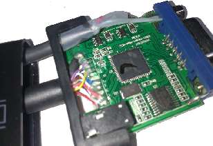
Once the wire to from pin 18 of the HDMI plug is out of the way, the red wire from the USB lead can be soldered into its place.
Here's the side the work was done to:
And here is the other side, note the abundance of tape to isolate things:
Check your wiring, then you can put everything back together by simply sliding the board back in, and placing the end cap back on.
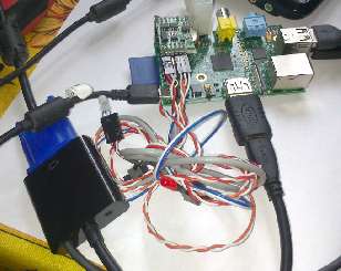
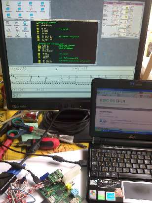
Here it is all back together and working, being powered from my eeePC:
This tells the Pi to output audio through the HDMI, to use the DMT resolutions, to select 1280×1024, and finally to disable the overscan. The result? A picture that nicely fills the screen.
Within RISC OS, I have set the resolution to 1280×960. There is no specific reason other than my being too lazy to find which monitor offers the correct resolution. 960 is "close enough". I think the GPU is scaling it to fit, as it looks okay on the screen, and as you can see there is a ridiculous amount of space on the screen. Being used to the 680×480 (ish) TV quality output, this seems insanely large. And it's a nice sharp crisp display.
The modification wasn't hard to do, the whole outlay did not cost much and the results are well worth it!
HDMI adaptor mod (USB powered)
Introduction
Using TV outputs with these little ARM SoCs is a bit tedious. Not so bad on the Beagle with its s-video, but pretty poor on the Raspberry Pi with its composite video - especially as the colour carrier merges to create jittering and interference patterns that I've not seen since I used the BBC micro with a television set!
In my case, the dongle contains a Lontium LT8511A which is a Chinese IC with, as is to be expected these days, very little public documentation. What we can tell from the sales blurb is that it can accept 1080p in 8/10/12 bit colour, it can output analogue up to UXGA (1600×1200) or HD1080 with three DACs (one for each primary colour). It contains a microcontroller plus its own EDID so it can interface easily with the host. There's an audio decoder that will take two channel I2S data and supply it to a standard 3.5mm audio jack. And it does a bunch of colourspace conversions for HDMI signals that are not RGB.
Everything all in for under twenty euros.
Why the mod?
The official HDMI specification says that the +5V supply on the HDMI is to be at most 50mA. It is intended for powering an EEPROM so the host can read the "EDID", a block of data that describes the display capabilities.
In the case of the Beagle, power is supplied by a polyfuse that is supposed to blow at 200mA. So obviously I wasn't keen to try the adaptor on the Beagle.
The modification, step by step
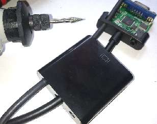
The first step is to get the adaptor open. This is, actually, remarkably easy. Just firmly grasp the HDMI cable and push it into the box. The cap on the VGA end will pop off and the whole circuit board can be slid out.
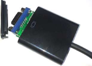
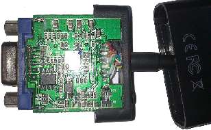
Here is the reverse side of the adaptor's board:
Strip off the shielding and wrap some tape around to isolate any that still shows. If there is a 'wire' protruding from the shielding, twist this round and merge with the black wire. As before, tape up anything that risks contacting with the circuit of the adaptor.
Once the 5V is in place, the GND wire can be placed. I soldered this to the shield lug from the VGA socket. It was the easiest place. Then, more tape to ensure nothing is going to contact stuff it shouldn't.
The HDMI adaptor in use
My monitor is an IISonic IIMJ7 with a native resolution of 1280×1024, so the settings in the Pi's config.txt file should be:
hdmi_drive=2
hdmi_group=2
hdmi_mode=36
disable_overscan=1
Zerosquare, 3rd August 2013, 16:50
"In the case of the Beagle, power is supplied by a polyfuse that is supposed to blow at 200mA." -> polyfuses are self-resetting fuses. They're basically polymer-based temperature-dependant resistors, with a sharp increase in resistance when their temperature exceeds a thresold; they don't blow when overloaded, you just have to wait a bit after the overload is removed, and everything is back to normal. So you should be able to test the adapter on your Beagle safely.Bryn Evans, 9th August 2013, 18:11
My reason was because I wrongly believed that there was not enough current from the Pi HDMI connection. This turned out to be wrong, as there was a sub standard (old) VGA cable in my set up that balked at the higher frequencies/lower output voltage from the Pi+Adaptor.
However it seemed a good idea to run directly from the powered USB hub and take the strain off the Pi.
Your article, giving the Configuration that you used inspired me to delve past the hdmi_safe setting and try again to match the TV used as monitor (1280x1024) more closely.
I found the Pi display a little fuzzy compared with the RPC.
After playing around with your settings I finally settled on using hdmi_mode=9 rather than mode_36
as his was sending the same type of output at the RPC was configured for. I now have a much crisper Pi display which seems to be a little brighter.
Having bought a second adapter, this time with audio,
modified in the same way, as the Pi seemed to be getting warm and there was only 4.7volts on the adapter board. Direct from the hub there is 5.05 volts.
So thanks for the tip about the working order of the HDMI Config settings.
Cheers - BrynAlfonso Ruiz de Lobera, 8th March 2016, 10:52
I guess I have burnt D1. But now I will fix evething in good order!!
Thanks!!Stephen Bennett, 11th September 2016, 14:54
| © 2013 Rick Murray |
This web page is licenced for your personal, private, non-commercial use only. No automated processing by advertising systems is permitted. RIPA notice: No consent is given for interception of page transmission. |