Rick's b.log - 2016/01/16
You are 18.191.189.124, pleased to meet you!
Rick's b.log - 2016/01/16 |
|
| It is the 24th of November 2024 You are 18.191.189.124, pleased to meet you! |
|
mailto: blog -at- heyrick -dot- eu
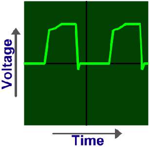
At its most basic level, the oscilloscope plots on its screen the input signal against time. The signal affects the up and down motion of a dot on the screen, and the time setting moves the dot from left to right.
On the converse, a digital oscilloscope will typically offer features such as the ability to capture erratic one-off signals (something that is practically impossible on an analogue model), zoom in to examine complex waveforms, save the waveform, print it, etc etc.
You will notice there is a lot of text about digital models, not so much about analogue. This is because digital oscilloscopes have some important technical caveats, and because analogue oscilloscopes are just inherently simpler.
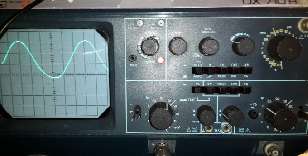
Let's first look at the oscilloscope:
My oscilloscope's specifications are as follows:
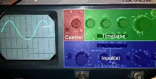
The oscilloscope is essentially broken down into four important parts, which are shown in this annotated diagram:
Let's look at these in more detail...
From left to right. The knob with the two arrows above is is for adjusting the horizontal position of the trace. Note that this is purely for aligning the trace on the screen, it does not permit you to choose other parts of the waveform.
Finally, we get to the timebase speed control. Broken into seconds, milliseconds, and microseconds, each option on this control (in the absence of the stretching control just described) corresponds to one horizontal division of the screen. The left-most setting, for example, is 2 milliseconds. This means each square across the screen represents 2 milliseconds, or 10ms for a sweep across the entire display.
To convert milliseconds to Hz, you should divide a thousand by the indicated time. For the 2 millisecond, that would be 1000÷2, which is 500Hz per division. If your waveform spans two divisions (such as a sine wave might), that would than be 500Hz÷2, or a 250Hz signal.
50ms is 20Hz; 1ms is 1kHz, 0.1ms is 10kHz, 50µs is 20kHz, 1µs is 1MHz, 0.5µs is 2MHz. Per division.
Using this, we can see that our timebase is on the 5µs range (200000Hz per division), and the waveform takes just over 6 divisions across the screen. Thus 200000÷6.1 gives us an estimated frequency of 32786Hz. Which is about right, as it is actually a 32.768kHz timing crystal from a clock. I was surprised to see a timing crystal giving a perfect sine wave, I had expected a square wave or somesuch.
Normal continual-sweep use is achieved with all buttons in their out positions.
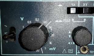
The knob on the left selects between AC component (the wavy line), DC and AC (straight line and wavy line), and 0V. Normal operation is DC/AC mode. The AC option can be useful for observing an AC carrier on a DC signal (by separating out the AC part). The 0V option is useful to set the 0V reference point.
As with the timebase, the voltage selection (running from 5mV to 20V) represents the voltage per division. You can see the control is set to 0.1V per division, and the signal in the topmost picture spans a little over 3 squares vertically; which means that it is 0.3V peak to peak.
The knob with the up and down arrows adjusts the horizontal position of the trace. For an AC signal, it is common to place the 0V on the centre line.
Dual trace:
XY mode:
How to use an oscilloscope
What is an oscilloscope?
An oscilloscope is an important piece of test equipment. Its function is simple - to take an electrical input and show you what it looks like. While this might sound boring, all sorts of problems can be diagnosed by simply seeing the signal. If it is supposed to be flipping at a specific frequency, is it? Is it missing anything? Are there disturbances (noise) in the signal that is being mistaken for data or triggering things at the wrong time? For a complex signal, such as a PAL television signal, you can see distinctive parts of the signal waveform, and then trace parts of it through the circuitry of a television as parts (field sync, line sync, colour burst, luminance...) are extracted and dealt with.
Types of oscilloscope
Basically, there are two types of oscilloscope. The analogue (cathode ray) type, and the digital type.
Analogue oscilloscopes are simpler to use, offer fewer fancy features (such as signal analysis and interpretation), tend to be cheaper than equivalent digital models, and provide a proper real-time display of input signals. Analogue oscilloscopes are best when dealing with real life analogue inputs or slower digital signals. Analogue oscilloscopes work by amplifying the input signal as necessary to cause the dot to move up and down the screen. As such, there is no issue of sampling resolution or data points, as it is analogue, and thus capable of the near infinite degrees of resolution offered by nature and physics themselves.
However, note that the display of a digital oscilloscope is sampled, processed, and then regurgitated so there is the problem that you may not be seeing what is really happening. If you measure a 20MHz signal on a 20MHz digital oscilloscope, you will be driving it at the end of its capabilities and there may be too few sample points (or too few per time domain) to show you that signal correctly - generally speaking it won't look anything like the same 20MHz signal as measured by a 100MHz oscilloscopes. In principle the effective range of an oscilloscope is half the maximum sampling speed of the acquisition system due to the Nyquist limit; however for proper undistorted signals, you ideally need an oscilloscope with a sampling rate four or five times greater than the maximum rate of the signal you want to examine. This is why you sometimes see insane speeds for digital oscilloscopes; a 100MHz model is best for 20-25MHz, and so on.
Add to that, many typical oscilloscopes have an 8 bit sampling resolution (256 discrete 'levels'). Those with greater resolution are considered "high accuracy", did you hear the "kerching!" sound as you read that? To put that starkly into context, the output from a CD is a 16 bit stereo signal. The audio waveform can use up to 65536 discrete levels. Thus, how can you accurately observe something as simple and commonplace as that which is present on the headphone jack of any CD player (or MP3 player, for that matter) when the oscilloscope itself isn't capable of that level of accuracy?
In the old days, there was a distinct lag between a signal happening and a digital oscilloscope showing it. This is less of a problem these days with ingenious contraptions such as the "digital phosphor" (I believe this is a Tektronic invention?) which can display a real-time trace. How this works is by having dual acquisition systems. One samples the signal and spits it directly to the screen as fast as possible, the other samples the signal at a better resolution and stores it in memory for the other functionality.
The parts of an oscilloscope
Here, we are going to discuss a fairly basic analogue oscilloscope, such as would be found in schools and the workbenches of geeks that don't do much electronics work (so can often pick up an ex-school model for a good price). The basic principles apply equally to digital oscilloscopes.
Typically you should expect to see eight squares vertically, and ten horizontally, with the central markers usually containing dashes to further subdivide the square into five sections along each axis, as can be seen from the pictures above.
Now something that is critical to understand is that all of the other controls are relative to the squares of the graticule. For example, if your timebase is set to 1 millisecond, that means that each division (square) horizontally represents one millisecond of time. Accordingly, it will take 10ms to traverse the entire screen.
Controls
On analogue models, the on/off control is frequently coupled with a brightness control in much the same way as older televisions used to have the power and speaker volume on the same knob. This is necessary as the faster speeds traverse the screen more and more rapidly which mean the trace becomes dimmer and dimmer. The brightness control can be used to compensate for this.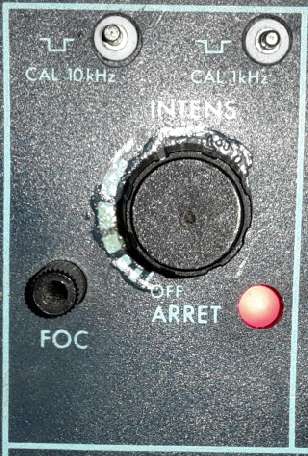
The tube focus is not locked as it is on a TV, so may need adjustment depending on the temperature of the cathode ray tube.
Finally, there may be one or two test points that provide a square wave at a known frequency. This is intended to be used for calibrating test probes.
Timebase
The timebase has two modes it can run in. Free running, or triggered. When free running, the controls select what speed the trace sweeps from left to right, and this will happen continuously. In triggered, a variety of options determine how and when to trigger and the oscilloscope will sweep the trace once (at the defined speed) per trigger. Of note is that when in triggered mode, nothing will appear when there is no trigger input.
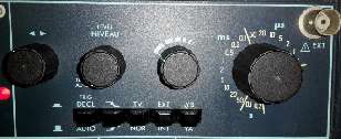
The Level knob (Niveau in French) is to control when the triggering happens, if using one of the triggering modes. Think of it as a sensitivity adjustment.
The next knob, with the dashed lines, is for tweaking the timebase selection. In its leftmost position (as shown), the sweep will be at the indicated speed. As the knob is turned to the right, the speed will increase until it is nearly the speed of the next faster timebase setting. This may be useful when you are not interested in the time, but wish to have a specific waveform fill the display for closer examination.
Triggering modes
Automatic mode (leftmost button, out) means the trace continually sweeps across the display. With this button pressed in (Déclenché in French), triggered mode is engaged.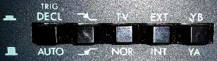
The second button selects to trigger on the rising edge (out) or falling edge (in) of the input.
The third button selects normal triggering (out) or a special TV mode (in) which will auto-trigger on every line sync.
The fourth button selects between internal triggering (out) or triggering by an external signal (in), the external signal being connected to the BNC socket on the upper right.
The final button selects whether the first input 'YA' (out) or the second input 'YB' (in) activates the triggering.
Input
These are the controls for an input signal. The signal is connected to a BNC socket just below the input controls, you can see this on the topmost picture.
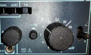
 The second input controls are very similar to the first, with the addition of a button (marked -YB) which can invert the signal.
 The first button (YA) pressed in selects to display the YA input on the display.
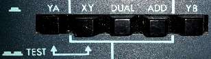
The second button (XY) pressed selects to have YA control the horizontal position and YB control the vertical position (and the timebase is not used).
If both of the two leftmost buttons are pressed, a special test mode is engaged. This will be described another time.
The third button (DUAL) pressed selects to display both inputs on the display as individual traces.
The fourth button (ADD) pressed selects to add the inputs together and display a single composite trace on the screen.
The fifth button (YB) pressed selects to display the YB input on the display.
Dual trace?
It is worth pointing out that most dual trace analogue oscilloscopes do not have dual traces inside the cathode ray tube. The way two traces are actually displayed is by using some trickery.
For the slower timebase settings (0.2s to 5ms on my model), the dual traces are created by rapidly switching from one position to the other as the trace passes across the display. By flipping back and forth, the illusion is of two traces on screen at one time.
For the faster timebase settings (2ms to 0.5µs on my model), the dual traces are created by displaying one trace, then the other, alternately. While this technically means that the oscilloscope is only actually showing you every other sweep, in practice it does not matter as the entire period for sweeping the two traces is 4ms, or 1/250th of a second - far faster than the eye is able to see. Faster indeed, than any domestic video camera stands a hope of seeing.
Using the oscilloscope
For viewing a single trace:
Never connect an unknown input with the oscilloscope set to its most sensitive setting - you risk damaging it!
David Pilling, 16th January 2016, 18:29
Bear in mind that usually the inputs will not be floating but referenced to mains earth, e.g. connecting USB +5 V to the low side of your 'scope input, will form a short circuit.
Similar fun if you use your 'scope on the mains supply.Rick, 16th January 2016, 22:08
Yes, two things I know never to do with oscilloscopes:
1, never connect them to the mains. It is possible with isolating transformers and such, but one really needs to know what they are doing.
2, it is not, and should never EVER be used as an ECG. It is potentially risky with battery powered digital models, trying to monitor a heart by probing with a mains powered analogue 'scope that has the shield side of the wire pegged to mains earth is a special sort of stupid. There is a reason medical ECGs are hideously expensive (designed not to fry the person being tested), and those cheap heart monitors available on eBay for a tenner use infra-red sensors to detect the pulse in a finger (no electrical contact). Milliamps across the heart? That's what a defibrillator does, and we all know what those are used for...
2b, related - it's not a brain wave probe either...Zerosquare, 17th January 2016, 23:21
Don't try that with a standard �10 probe, this is dangerous; you need a special high-voltage probe. But, as you mentioned above, if you're doing this kind of stuff, you better know exactly what you're doing.David Pilling, 18th January 2016, 02:44 David Pilling, 18th January 2016, 18:26 Rick, 19th January 2016, 20:17
By contrast, the mains at a mere 230V (EU) or 110V (US) [other places may vary] is enough to kill a group of people holding hands stone dead.
How? It's the CURRENT. A few milliamps around the heart and you're screwed. A mere 10mA can cause a severe shock. Above about 50mA and you become a corpse. A decent trip switch will kick in at 35mA so you'll learn not to do that ever ever again, but should survive. Should. Sometimes they just aren't quick enough.Rick, 19th January 2016, 20:22
And secondly, the mains is AC. This means it switches polarity fifty (or sixty) times every second.
Imagine being smacked in the face with a claw hammer. Now imagine being smacked in the face with a claw hammer fifty times a second. That's what the mains is like to your body...
(ps: ouch)Rick, 19th January 2016, 20:35
There.
Did I miss anything?
| © 2016 Rick Murray |
This web page is licenced for your personal, private, non-commercial use only. No automated processing by advertising systems is permitted. RIPA notice: No consent is given for interception of page transmission. |