Rick's b.log - 2016/12/19
You are 3.17.179.132, pleased to meet you!
Rick's b.log - 2016/12/19 |
|
| It is the 21st of November 2024 You are 3.17.179.132, pleased to meet you! |
|
mailto: blog -at- heyrick -dot- eu
Uhhh...
Though, actually, this year something has arrived that I can talk about. Probably most of the days.
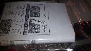
Here it is:
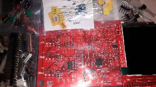
Confused? Let's try it with its parts open:
Has that made it clearer for you? A little board, an even littler LCD panel, some bags of bits. The writing you might see in the first picture is because I've checked off all of the parts.
It is a JYE DSO168 "oscilloscope" kit. Though given this one arrived with photocopied instructions and no serial number label, it's a Chinese knock-off of a JYE 'scope kit.
That said, the version I have is the one with the fiddly SMD parts pre-soldered to the board, and it seems to be reasonably well put together. That said, it was supplied with all the bits stuffed into a plastic bag, so god only knows how that goes with respect to static electricity.
It kind of sucks to have bought a clone, however trying to find an accessible legitimate seller on Amazon(.fr) is harder than it should be. JYE's website (after looking later on) suggests a retailer calling themselves "Banggood" on eBay (but, you know, didn't want to go via eBay). I dunno about you, but if I was trying to avoid dodgy dealers, I'd have stayed away from a company calling itself "Banggood" - it just screams "Chinese clone" to me. Yet, "Banggood" is good, while "SainSmart" is not?
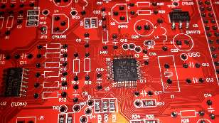
Gratuitous "arty" shot of the main board:
The heart of the 'scope is an STM32F103C8 (with a unit price of $2.056 per 10,000!). This offers an ARM Cortex-M3 running at 72MHz, 64KiB Flash, 20KiB SRAM, RTC (if given a backup battery), 2 ADCs each capable of converting 0 to 3.6V in 1µS with 12 bit accuracy (1023 levels). I/O in the form of SWD debug, UART, USB 2.0, GPIO etc. Three 16 bit timers, plus a PWM timer. Plus a load more stuff (IIC, SPI, etc). It looks like a pretty hardcore little chip, actually.
Looking at the schematic, the design of the 'scope seems to be fairly simple. A lot of it is involved with conditioning the input so that whatever it may be that is input is stepped down to something that can be input into the ADC. The senstivity is controlled by two switches. The first selects 10mV, 0.1V, or 1V per division; while the second selects ×1, ×2, or ×5. This means the least sensitive option is 1V/div ×5, in other words, 5V/div across ten divisions. Or 50V maximum input. The most sensitive is 10mV/div ×1 which gives us 100mV from top to bottom of the screen; though to be honest I can imagine there may be a fair amount of ripple in a signal that is trying to measure mV with an ADC set to measure 0-3.6V, with the central 0V position being 1.6V (so it can measure swings +ve and -ve).
A resolution rate of 1µS would imply a raw capability of handling signals up to 1MHz (1000KHz), however taking a one-shot reading of a value is the absolute worst way to do things. It is better to oversample, take several readings, and average them. This will lower the speed at which the device is capable of working, while improving accuracy. The DSO138 claims to be capable of recording signals up to 200KHz (5µS), though videos I've seen on YouTube suggest that this is optimistic.
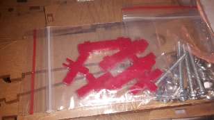
We'll see how it goes. I hope it works out, as I also got a dinky little plastic case for it. Here it is as a bag of bits:
The board that I purchased claimed to be the later version (13803K), while the instructions were for an earlier version (13801K). Thankfully the only difference is the modification of one resistor (was 1.5KOhm, is now 150ohm), and they included both types in the pack. Plus a 29µF ceramic capacitor...though I'm not quite sure why as there is no capacitor of that value in the schematic. Hmmm?
Day XIX
Not many more to go. Hasn't time passed quickly?
What to write about next?
The problem with setting yourself a challenge to write something every day in a month, when something like an Advent Calendar (or three!) can take up the first twenty four days, is what the hell to write about afterwards. Christmas is covered. I can take some photos (as usual), talk about what I eat, that sort of thing.
That still leaves six days.


So maybe if JYE didn't want so many hassles regarding fake kits and customers not knowing what was what, they should perhaps have more clearly legitimate distributors on places like Amazon, and not have overseas distributors applying markup that would imply shipping from the US might be cheaper than buying locally!
Let's look at it like this - JYE's "official" (US) distributor seems to be AccuDIY, and the product is listed here as $36 plus an extra $4 for the pre-SMD soldered version.
Their French distributor is Selectronic, who list the kit at €49,95, and you can count on another €6,90 for delivery.
Something in the ballpark of €35-40 is in my budget, though I'd need to think about it. Something closer to €60 is not in my budget. Twenty more than that gets one a basic entry level pre-built USB 'scope. It's a lot to ask for a kit.
Me? It was €25 with free postage for the 'scope kit. A kit, I should add, that advertised itself exactly as "JYE DSO138 2015 DIY KIT".

The circuit itself is actually pretty simple (hence why I imagine I'd be able to put it together). The intelligence takes place in the firmware.
Is the DSO138 a "toy"? Well, yes and no. It is going to be useless if I want to probe around inside my BBC Micro (expect 1MHz or 2MHz clock rates), but where it might be more useful is in examining serial or IIC data. MIDI, for example, is 31.25KHz. But, then, note the "DSO" in the title. A signal, when triggered, can be recorded by the 'scope and then held for examination. It's apparently a bit fiddly, but then we're looking at a ~$36 (legit price) kit, not a fancy Tektronix costing that with two zeros at the end.

David Pilling, 20th December 2016, 02:10
Good luck with the kit. I built the 'pigoscope' which is what the STM32 community called their version. However that has no analogue front end so no great bandwidth.David Pilling, 20th December 2016, 02:23
Sampling at 1MHz Nyquist would say max signal rate is 500KHz, although it is a rough calculation with many catches.
| © 2016 Rick Murray |
This web page is licenced for your personal, private, non-commercial use only. No automated processing by advertising systems is permitted. RIPA notice: No consent is given for interception of page transmission. |