Rick's b.log - 2016/12/21
You are 3.140.198.201, pleased to meet you!
Rick's b.log - 2016/12/21 |
|
| It is the 21st of November 2024 You are 3.140.198.201, pleased to meet you! |
|
mailto: blog -at- heyrick -dot- eu
The resistors were determined by metering them. This is essential because brown-red-black-black-brown is 120 ohms +/- 1%; while brown-black-black-red-brown is 10K ohms. Yup, the exact same code the other way around. Useful, that. Grrr.
I hit something of a brick wall when trying to meter the diodes. My multimeter beeps with the leads shorted, reads zero with the leads unconnected. And with the diodes in either sense, it claimed they were all open circuit.
Well, either it has failed or something up with my meter. On to plan B.
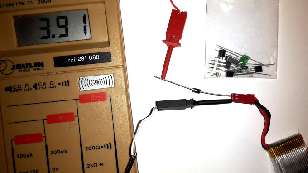
The next test was to check the 1N4004 diode by hooking it up to my drone's 3.7V battery and seeing if the voltage is readable in only one direction. Short answer - yes. The diode is good and the multimeter is weird.
The final test was of the 1N5819 diode. This one is a Schottky rectifier, and this one is extremely strange. With a diode, one might expect to see nothing passing in one direction, and current passing in the other direction. It's sort of the basics of how AC gets converted into DC. Look up "bridge rectifier" if you're interested.
Ready for the weird? Here it is in the reverse sense. For a normal diode, this ought to read open circuit, as in "no connection":
About the fake reports... KYE got back to me quickly to say thanks for letting them know. Just checked my email and Amazon got back in touch to say:
Here's that again, this time translated:
I have a choice of wrapping up the kit and sending it back at Amazon's expense, or contacting them to request a replacement. I'm not sure if I should send back the kit in the latter case, as the action of sending it back will trigger a refund (a separate email contains instructions on returning the product for a refund...). I have asked for a replacement, see how that goes - because I think you and I both know that it's quite likely the rest of the stock is equally fake.
So... it looks like I won't be building an oscilloscope over the winter holiday (unless I want to lose €25 on a clone when they're so up-front about giving me a refund). Well, bugger. What's the glyph code for an unhappy face?
Here's what should have arrived:
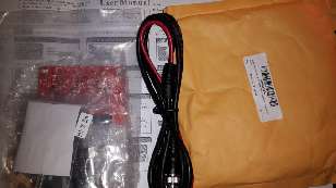
Here's what did arrive (note plastic bag (antistatic?!?), padded envelope (no box), and photocopied instructions):
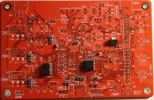
Now let's look at the circuit board itself. Here is the one pictured on the listing - it's a legitimate KYETech board:
Here's what arrived, wanna play "spot the difference"? :
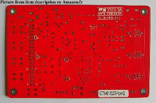
Here's the back of the board as shown in the listing, you can see there's a KYE serial number affixed:
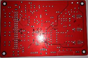
And note the big empty space in what arrived:
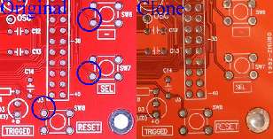
And for the final photo today, definite proof that the board is a fake and not as advertised. The tracks leading out to items such as the button or certain test pads are teardrop shaped. You can see this in the close-up on the left, from a legitimate board. I've put blue circles around the parts I'm referring to.
Day XXI
Three days to go, then I can ditch this stupid roman numerals nonsense. ☺
Component testing
I have no way of testing the capacitors or inductors, other than looking at what it says on them. The power inductor is supposed to be 1mH at 0.5A rating, but all I can see written on it is "6FR-H" which doesn't seem to match anything logical. Note that the "6" might be an "S" as only the right half of the character is visible.
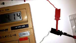
Anyway, the Schottky is not something I've ever really come across before. So here's the forward voltage reading - it's barely different from what the battery is providing (compare with the 1N4004 above, that drops about a quarter volt):
 You will notice that the final digit is slightly blurred. This is because the voltage that I observed started around 3.5V and just kept dropping slowly. I wonder if this diode is faulty, but on the other hand maybe this is expected behaviour? I say this based upon the fact that the diode hasn't failed short circuit - the voltage on the reverse biased side changes.
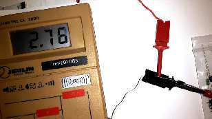
Has anybody performed a similar test with this type of diode? Is this behaviour consistent with expectations?
Nous vous confirmons par ailleurs que les vendeurs tiers ne sont pas autorisés à vendre des produits substantiellement différents de ceux décrits dans l'offre.
J'ai toutefois transmis les informations que vous nous avez fournies au département concerné afin qu'il fasse les recherches nécessaires.
Nous serions heureux de vous proposer une commande de remplacement cependant, nous préférons nous assurer que le reste de notre stock ne présente pas le même défaut. Toutefois, nous ne sommes pas en mesure de vous indiquer sous quel délai ce type de recherches peut être résolu.
We also confirm that third-party vendors are not permitted to sell products substantially different from those described in the offer.
I have therefore transmitted the information that you have provided to the department concerned so that it can carry out the necessary research.
We would be happy to offer you a replacement order, however we would prefer to ensure that the rest of our stock does not have the same defect. However, we are not in a position to tell you how long it will take for this sort of research to be completed.How to tell a fake's a fake
Comparing photos on the Amazon.fr listing with reality.


One the right, the same part of my board. Thing is, making teardrop tracks is fiddly, so clone boards don't bother. And, you know what? It's actually really obvious when you know what you're looking for:
David Pilling, 23rd December 2016, 00:01
When it comes to testing, depends what you're testing with, if your ohm meter uses 0.1V a normal diode is going to look open circuit. If you test a Schottky with a tiny current it will appear to leak.
The best thing ever is the "transistor tester" which is an open source project based on the ATMega 328 - Arduino processor. These come from China 10 quid a throw, based on a project by someone in Germany. Anyway stick in any component it will tell you what it is, and the values. Transistors, inductors everything.David Pilling, 23rd December 2016, 13:30
Seems like you're using the voltmeter range to measure diode current. As they say the voltmeter is the most sensitive current meter you will ever own. That's why you're getting a forward drop on standard diodes around 0.2V. Schottky does have some capcacitance and if you might just be seeing that charge.
I've told you what I'd do - but if stranded without kit, I would get a 1K resistor, in series with meter on 20 mA range and diode and battery. Or diode, battery, resistor in series, measure voltage across diode.
Way back I'd test transistors with multimeter, its not that hard but stick in modern "transistor tester", press button, done.
These ...testers its a bad name, people think only transistors, had someone come up with a snappy name would be much easier.
| © 2016 Rick Murray |
This web page is licenced for your personal, private, non-commercial use only. No automated processing by advertising systems is permitted. RIPA notice: No consent is given for interception of page transmission. |