Rick's b.log - 2017/09/17
You are 3.21.12.88, pleased to meet you!
Rick's b.log - 2017/09/17 |
|
| It is the 24th of November 2024 You are 3.21.12.88, pleased to meet you! |
|
mailto: blog -at- heyrick -dot- eu
I was going to write something, but after Friday and Boris pledging the non-existent £350M to the NHS (and what to rural development, what to farmers, what to...?), having just returned from the British islands in the Caribbean where he had to deflect the accusations of a shameful response to hurricane Irma, having decided that the island's occupants are "too wealthy" to receive aid funds, because absolutely everybody on the islands is a billionaire.
Sorry. No. Just no.
So no.
I have some replacement cable, with the required RJ11 plug, from Amazon and a length of plastic wire shielding (a grey tube) from a local DIY store. This will permit me to reconnect the rain sensor. It is dead easy, the centre two wires of the cable connect to a reed switch. That's it.
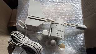
The wind sensor was going to be more of a challenge. I had spliced and taped the cable, but it only worked sometimes. Because the wind sensor is a little computer that collects the information to send back to the outdoor transmitter. I was looking at breaking the old cable near the sensor and splicing in a new length of cable. As I was tidying up the sensor in preparation, the remains of the rubber ring fell off the wind speed gizmo. Well, it turns out that said gizmo was a magnetised piece of rubber, and it turning is what registered wind. So, yeah, nice one La Crosse, using a flimsy bit of rubber in a device mounted outside exposed to the elements.
Turns out that just as I needed a replacement part, a French guy was selling one on eBay. It's the slightly later model with the little spinning buckets underneath:
I will need to buy a thicker cable shield (big enough to pass an RJ11 plug through as the cables are fitted directly into the sensors) to protect the cable, and then hook it all back up. Not this weekend. Maybe next...?
We had planned to go to a couple of vide greniers. The weather had other plans.
So I sat down and measured out all of my components. Yeah, that's most of it. Sixteen resistors, four capacitors, three electrolytics, four push buttons, one rotary button, and a couple of connectors the most complicated being a 2×5 header. I thought that this would be an absolute doddle compared to the DSO 138 I built last winter.
Mom asked me if building it was saving anything over just buying one pre-built. I told her that it was only available as a kit, as the part where you build your own piece of test equipment - that's the interesting part. I guess if it was available pre-made I could pay a few euros extra for a built one... but where's the fun in that?
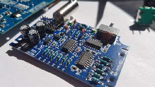
Some things needed attaching to the main board, but most of the work was in adding components to the analogue daughter board. Here's mine built - and in keeping with my desire to have a working device first time around, every piece was checked and metered (if applicable) again before committing it to the board with solder.
The next stage was to calibrate the oscilloscope. We are used to calibrating a trimmer in the probe on 10× range. This oscilloscope also needs calibration for much the same thing. I calibrated it to my proper probe as that is probably what I'd be using. That said, tweaking the two variable capacitors (as applicable for the selected range) had no visible effect whatsoever, but since the trace showed a nice square waveform, I didn't concern myself with it.
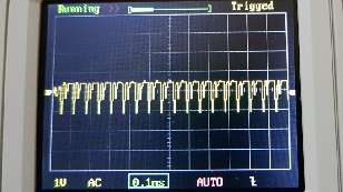
And here is the finished oscilloscope failing to be quick enough to deal with a PAL video signal. But this isn't a surprise, it's the same processor core as the DSO 138. As it turns out (confirmed on the JYE forum), on the 10µS and 20µS settings, the firmware uses interpolation. Essentially this means that the gaps between sample points are "reconstructed". The simplest form of this, and likely what the JYE DSOs do, is to draw a straight line from one point to the next. This more than likely explains the weird sync pulse and the completely missing colour burst in the video waveform.
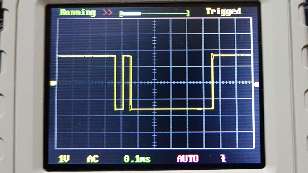
Something I noticed was that the scope seemed to have difficulty reading the frequency of the test signal. Looking at the far left of the display indicated an erratic pulse:
It would be valid to say there was a fault in the triggering, but there doesn't seem to be a visible issue when using the same settings to view an external waveform, in this case my trusty video signal. Why always a video signal? Because it is distinctive, larger values than audio, and the composite video feed to my USB capture dongle is right in front of me and easy to hook in to. That's why. ☺
It could be something as simple as the test signal being created in software, instead of a free-running counter or somesuch. Unlike the DSO138, this test signal has an option to be switched between the usual 3.3V and 0.1V - and maybe the start of setting up capture for writing across the display has a knock on effect on the timing of the test signal? It's just a guess...
In use, the rotary knob helps quite a lot when setting things up. Pressing the button for fast mode (indicated with ">>" at the top of the screen) makes it a lot faster to change the horizontal position of the recorded waveform. This was so slow as to be nearly useless on the DSO 138. Now it is practicable on the DSO Shell. Ditto for setting a trigger position (little arrow on the right). I miss the "trigger voltage" readout, the top right of the display now says "WAITING" or "TRIGGED" since there is no longer any LED to flicker (actually there is, but it is buried inside).
Maybe JYE's next incarnation will run the two ADCs in dual continuous mode (to give half µS sampling, and double the effective bandwidth?) and swap a slightly larger case for the option of having some sort of battery inside?
At any rate, for those who would find it interesting to build their own 'scope, I would strongly recommend this kit. With only 16 resistors to meter, seven capacitors, and a bunch of other bits, it is pretty simple to assemble. Accordingly, it worked first time for me. I would have counted anything less as a bit pile of fail on my part.
Looking east in mid August, moonrise. The two stars above are Hamal (left) and Sheratan (right) of the Aries consellation.
Looking north. Ursa Major is clearly visible. Leftmost is Alkaid (sounds like a heartburn remedy), then Alcor, and Alioth to complete the handle. Next is Megrez, then down to Phad, over to Merak, and up to Dubhe. Yup, while we in "the West" were navel-gazing, the Arabs of antiquity were looking up and naming the stars.
Looking up. The two brightish stars towards the bottom are Deneb (left) and Sadr (right) of the Cygnus constellation. The really bright star towards the top is Vega (Lyra). To fit this into the previous picture, Polaris would be off the bottom left of the image. The two stars of Cygnus draw a line parallel to the south east, and Vega is south-south-west. How? Because, as I said, we're looking straight up.
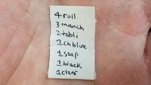
So I went into stock like I tend to do from time to time, and said to the girls there that I had a small list of things to get...
That's my hand.
And, yes, it is franglais, as it is a list for me to remember, not for anybody else. Not that they were capable of reading it...
BrExit
No.
My bullshit filter exploded on Friday, leaving little bits of burning wreckage all over the room.
Weather station
Those of you who may have looked at the reports from my weather station recently might have noticed that there are no recordings at all for the wind and rainfall. This is because something has been eating the cables. Biting right through, fairly clean cuts. I don't know if it is mice, crows, or annoying pixies. Either way, the sensors have been cut off.
DSO Shell

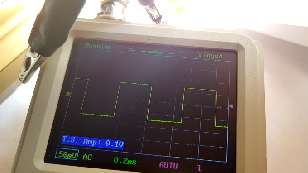
That said, it would be interesting to know what the real honest sampling rate actually is. The schematic indicates that only ADC0 is used, which means we will be looking at 1,000,000 samples per second maximum. The ADC is most likely running in continuous conversion mode, meaning it free-runs and interrupts (or uses DMA) at the end of each conversion. When in the 10µS range, each square on the screen represents 10µS in time, so each pixel within the square should be 1µS - which is the physical conversion rate of the ADC. However for complicated maths reasons that basically amount to decreasing noise and improving accuracy, it is usual to sample the same data point multiple times. The manual says that its effective bandwidth is 0-200kHz, which suggests that five samples are taken for each data point (they are probably averaged), which would give us our 200kHz bandwidth. This means that in the 10µS mode, there would only be two data points per square across the screen. A look at the screen below indicates that this is not the case. It looks as if there may be five data points per square (sampling each twice) and then basically guessing to fill in the missing samples. It is possible that in the fastest timebase, the firmware trades accuracy for speed?
More interesting things happen when looking at fast signals (such as the test signal) in slow timebases, including ones where the sampling rate coincides with the input 1kHz wave always being high or always being low, meaning the signal would simply disappear and become either a solid 3.3V or a solid 0V. Indeed, translating an analogue signal into a digital value is a complicated thing.
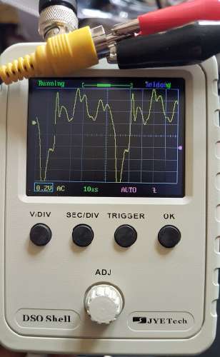
The device is really small, a little over half the size of the DSO138 in its case. As I said, it is a shame that no provision was made for running it from a battery pack. There is actually an optional header (two solder joints, so I fitted it) for plugging in some sort of battery, but such a battery would probably have to be taped to the underside.
Astrophotography
All pictures taken with my Samsung S7 in long exposure mode - 8 second exposure, aperture f1.7, ISO 800.
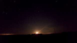
Polaris, the pole star, is not in this picture. It is just off the top. If you take the line formed by the two rightmost stars of Ursa Major and keep on going up until you reach a bright star, that's Polaris.
You can also see the trail of a UFO. It was on its way to molest cattle in Ohio until one of the green slimy blobs pointed out that the captain was reading the map wrong and they were currently in France. Funny, they can travel between galaxies, but can't find their way around a backwater planet that amounts to little more than a cul-de-sac filled with peculiar life forms, some of which keep claiming to be intelligent yet they have not managed to venture beyond their own satellite thanks to the stupid saps still thinking that "big explosion" is how space travel is supposed to be done. But the blobs will content themselves with messing around with cows because they've seen our movies. They know that America is in charge of everything, and what America isn't in charge of, it blows up. The cats told them so. Cats, those clever aliens that have successfully infiltrated this nowhere planet. When cats give you "that look" (you know the one I mean), it's because they already know what subatomic particles are made of, they already know the truth about wormholes (how do you think they got here?) and we - the "advanced" species is talking to cat in much the same way as we talked to pre-toilet-trained humans. The small ones. The ones that make a lot of noise. If we learned and spoke cat, then we'd be smart. But we don't, so we aren't.

And finally...
I am known at work for writing very small. I also enjoy a good visual gag.
It's written on a sticky price ticket.
Zerosquare, 18th September 2017, 09:41
Nope, even without averaging, bandwidth of a sampled signal is at most half of the sampling rate:
https://en.wikipedia.org/wiki/Nyquist_rate
That's a theoretical upper bound, and it would require perfect analog filters which don't actually exist.
Another factor is that even if it was possible, you'd only get two samples per signal period, which is too low for any useful visualization.
So a factor of five between sampling frequency and max signal bandwidth is pretty typical for oscilloscopes (at least those whose manufacturers are honest). For example, the one I've got here samples at 1 GHz and claims a 200 MHz bandwidth.David Pilling, 22nd September 2017, 22:44
These kit o-scopes are fun and you could do a lot with one. But not to be compared to many 1000 quid professional equipment.
Interesting that modern digital scopes can do things that the old scopes of years past could not, but they are not necessarily as good when it comes to bandwidth and sensitivity. Sometimes valves can beat computers.
(oooh secure)
| © 2017 Rick Murray |
This web page is licenced for your personal, private, non-commercial use only. No automated processing by advertising systems is permitted. RIPA notice: No consent is given for interception of page transmission. |