Rick's b.log - 2019/05/05
You are 3.143.17.224, pleased to meet you!
Rick's b.log - 2019/05/05 |
|
| It is the 18th of December 2024 You are 3.143.17.224, pleased to meet you! |
|
mailto: blog -at- heyrick -dot- eu
So I did that, Saturday a week ago. The shop was "Bricomarché", a French incarnation of something like B&Q.
The woman suggested that he try another, so he went in search of another socket. No dummy!, the woman said, she meant to go get another receiver.
So he did. Amazingly two years later they still had this model in stock. Useful for me.
A few moments looking at my receipt, and wandering off with it - most likely to take a copy of it. Then he came back, dumped the new receiver into its box and handed it to me.
And that was that.
Wow. I expected it to be more complicated. Or is it only England where it is necessary to quote the Sale of Goods Act to retailers?
You can read about Minitel and the basics of its operation and hardware in my article on the 1B model.
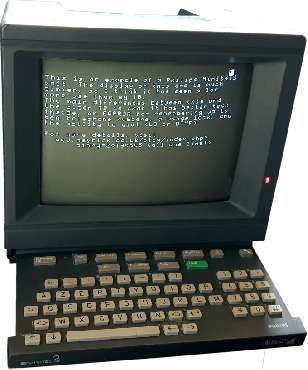
This, then, is the model 2. With a build number beginning "89", I would imagine that this was made in 1989. It differs from the earlier 1B by:
In common with other Minitel, the device itself is basically a dumb terminal that works either in a 40 column teletel (viewdata-like) mode, or a sort-of VT100 80 column mode. It is capable of interpreting a number of control sequences for things like character placement and intensity, but it does very little with the received data other than to display it in some manner, and as for outgoing data, that;s sent to the host. A quirk of the Minitel is that you can enter (some) characters when the device is not connected to anything, however it has no special intelligence. It is basically a screen and keyboard to connect to a remote computer. All the clever stuff happens on the server.
As before, it has an eccentric keyboard layout; this time offering a 'power' key. This is because the Minitel2 is always on. When in use, it consumes around 35W. When in standby, the screen is turned off, and it is a sign of the age when it was built that the user guide proudly informs one that the device "takes less than 10W when in standby". 10W? While doing nothing? That's deplorable!
Also as before, it is a small and ridiculously shiny nine inch monochrome display. As it is a Philips design, it's a Philips tube. In this case an M24-514W.
As before, the Minitel was easy to open (two clips under the handle, and two on the bottom) and consists of two boards. A power and video board mounted vertically in the side, and a horizontal processor board.
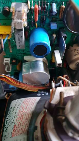
Here is a photo of part of the power board, with the tube label visible in the foreground. At the bottom of the power board (to the left of the big silver can) is a fuse. You will notice just above that the mains plugs in directly to that. There is no pop out power conditioning like in the 1B.
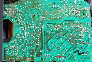
Here is the back of the power board. It indicates the high voltage and low voltage parts, but I can see five potentiometers (asides from the main brightness control) and there's not a hint of a clue what they're for.
Here is the main board. As you can see, there's less stuff inside, such are the advances of technology.
First in the middle is the EPROM holding the Minitel firmware. My version is "Bv3". It seems there are many incarnations: Jelora has Bv9 (dump, hosted on his site - it's a 32K dump with a little under 18K used), while HxC2001 has Bv4 (dump, hosted on his site - it's a 32K dump with exactly 16K used).
The processor, to the right of the EPROM, is an 80C32 which is an enhanced ROMless version of the 8032. It contains 256 bytes of RAM, a UART, various timers, and PIO pins. If it is clocked from the video controller clock, it will be running at 14.31818MHz. You'll notice the space for the processor's own oscillator (to the upper right of the processor) is unpopulated.
Upper left of the board is the video circuitry. This time the video controller is a TS9347 which is pretty much the same thing as ED9345 used in the earlier terminals. It supports a number of enhancements, obviously, such as 27 additional characters. The first 16 of the G0 set appear to be different in places, as are some of the the G0E extension characters.
The tiny chip by the keyboard ribbon cable is an SN74LS145N which is a 1-of-10 decoder/driver open-collector. In essence, it accepts four (BCD) inputs and uses that to select one of ten outputs, to allow the keyboard scanning to be performed using fewer output pins. There are 67 keys on the keyboard (basic AZERTY, numeric, a row of symbols, cursor/shift/Ctrl, and the Minitel function keys), which would imply that the keyboard is based upon a nine-by-eight matrix (72 keys). The nine way will be the output pulses (from the 145 chip), leaving the eight way return back to the motherboard to be either fed into one of the PIO ports or, more effectively, passed through some sort of shift register. This could reduce the 17 I/O pins implied to maybe 6. Or two if you do a cute trick like controlling the 1-of-10 decoder by hooking it into the address bus and accessing it by writing dummy data to specific addresses.
Upper right is interesting. The TS7514 is a V.23 modem with DTMF tone dialling, line status monitoring, and automatic gain. It replaces all those odd ICs on the older terminals and adds the ability to manage the line for itself - which I'm sure to many was a very good improvement on the older devices (where you had to dial on a telephone, start the connection manually, then quickly hang up the telephone so it didn't mess up the connection).
The last thing of note is just between the speaker and the microprocessor. It's a tiny IIC controlled Serial EEPROM offering 256 bytes of storage (rated for 1 million erase/write cycles and 40 years data retention). This is where the password, settings, and phonebook are held.
In terms of what to do with this device, probably (some day) much the same as before. To have it as a serial terminal for aiding debugging? The enhancements in this version mean that the serial port can run at 9600bps which is twice that of the 1B's. Unfortunately it's still a weirdo serial connection, so I'll need to send off for an interface cable.
Here's a video of me calling Jelora:
And to blow your mind, HxC2001 has used the Small Computer Compiler to write some code, in C, to run on the Minitel (replacing the normal EPROM, obviously), and... holy hell. I wasn't aware that it could act as a bitmap display. Feast your eyes upon this:
Satellite receiver replaced
I wrote in the previous entry that my satellite receiver had died, and that it had a two year guarantee.
I sent an email to Metronic, who promptly replied telling me that for "SAV" (service après vente, or after sales service), I was to take the box back to the retailer that I bought it from.
The woman at the reception desk called for the man who deal with the tech things. I explained that when it was plugged in, no little red light came on as it was expected to. He took it and plugged it into a multi-way power strip. Nothing happened. He examined the device, in case there was some sort of hidden power switch. He even peeled back some of the plastic coating in case it was under there (!) but, nothing.

So he opened the box, plugged it in, little red light.

Minitel 2
Today, vide grenier (ta-dah, bet you totally didn't expect that! :-p), I found a granny selling a Minitel 2 for the lowly price of a crisp tenner.
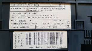
Unfortunately my one seems to be rather dim - I can only imagine that it has had a long life seeing much use. However unlike the Telic model, the Philips device does not have any sort of diagnostic information printed on the circuit board. Maybe there's a variable resistor that I could twiddle to bump up the brightness more than the big one on the back would permit? Who knows!
It is worth noting that in the teardowns of both Jelora and HxC2001 (links below), both of them appear to have Samsung 240AG4 tubes. Are they interchangeable? Was the Philips tube not as good?
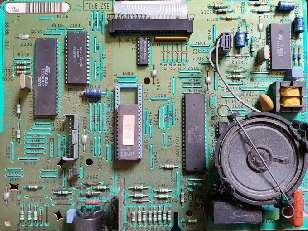
The 87C257 is a UV erasable EPROM of 32KiB size. It is socketed to allow for upgrades to be possible, and it looks like there is provision (perhaps by altering some of the many wire links around the socket) to insert larger EPROMs.
In keeping with the idea of the Minitel being a dumb terminal, the processor only has 256 bytes of RAM available, while the video controller has an 8K SRAM (D4168C) to store the characters for display on the screen.
Rick, 9th May 2019, 09:15
The "graphics" are an array of ordinary characters on the screen, which are set up as redefinable characters. Then, these characters (on a, what is it, 7x9 matrix?) are redefined on the fly, giving the illusion of a bitmapped display. It's actually quite clever.
https://youtu.be/5RosdIeMPecDavid Pilling, 12th May 2019, 13:38 David Pilling, 12th May 2019, 13:39
| © 2019 Rick Murray |
This web page is licenced for your personal, private, non-commercial use only. No automated processing by advertising systems is permitted. RIPA notice: No consent is given for interception of page transmission. |