Rick's b.log - 2019/05/08
You are 18.188.63.71, pleased to meet you!
Rick's b.log - 2019/05/08 |
|
| It is the 21st of November 2024 You are 18.188.63.71, pleased to meet you! |
|
mailto: blog -at- heyrick -dot- eu
This isn't actually a great surprise. While the Minitel terminals were built fairly well, they were given to telephone subscribers (one of the strengths of the service and possibly what made it the largest public computer network in the world until the internet exploded in popularity) so they had to be built to a budget. The quintessential Minitel terminal is a nine inch monochrome screen in a thing that looks like a small television set, with a flip down or slide out keyboard, and a phone lead. Inside was a V.23 modem capable of 1200/75 baud. That means 1200 bits per second one way, 75 the other. Roughly, divide by 9 or so to get the data speed in bytes per second. To put that in perspective, downloading a 704MiB ISO CD image at that speed would take just a little under 57 days. Oh, and there's practically zero error correction.
Luckily for us, electronic components and picture tubes can vary. Therefore the brightness setting on the back is just a user control for tweaking the screen intensity to personal preferences. Inside there will be a master brightness control that is adjusted for each terminal during the build process.
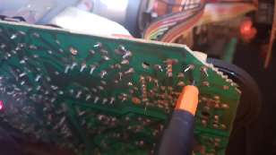
It just so happens there's a variable resistor right in the expected place, so let's shove a screwdriver in and give it a very gentle twiddle.
Yup, that was it. So if your Minitel 2 suffers from a dim or faded display, you can use this adjustment to bump up the brightness. It's the variable resistor that's practically hidden underneath the big brightness setting wheel (which is why I'm adjusting it from the other side of the board).
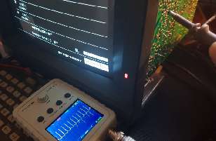
I MUST POINT THIS OUT: You see those ribbon cables going to the neck of the cathode ray tube? They are very close to the thing you're adjusting. Be aware that the cathode is likely to be charged at around a hundred volts, the grid (that's the part you're adjusting) will be something in the range of 40 to 100 volts. And the first anode? You're looking at two to three hundred volts. So do not take any chances or act a wally. You will regret it.
Okay, theory over. Just know that CRT displays contain some crazy voltages inside.
Since I was there, I noticed that the ribbon cable connecting to the motherboard does not appear to be documented anywhere, and unlike the Minitel 1B, there's no useful indication on the motherboard.
So, time to take out my tools and prod around, see what's what.
Here's what I discovered:
Or, in plain HTML... Pin 1 is at the top of the power/video board, and is a black cable on the outside of the socket (each colour is doubled). This connects to the motherboard with this pin closest to the rear.
I've not probed around to determine which signals are to the motherboard, and which are from it. To my mind, it looks fairly self-evident: +5v, +14.2v, and -12v are to the motherboard; while video, and the two that change when in standby are from it. One may be to bias the LED to change its colour, while the other may inhibit the power to the cathode ray tube. That's a guess, mind you.
Minitel fix
I mentioned how the Minitel 2's display was very dim, dim enough that I had to use it in a dark room, and dim enough that the graphic diagram of Jelora's demo did not show any background on the left hand side.
Anyway, I put all of this here so you can get an idea of the sort of era of technology we're talking about.
And maybe it would become clear how old stuff can start to wear out. Like people, really. ☺
On a fairly simple monochrome design such as the Minitel, we'd likely be looking for a small potentiometer somewhere near the big brightness control.
Oh, and that big cable attached further up with the rubber cup? Don't ask. A cathode ray tube basically takes electrons emitted from the cathode. That little lamp you see glowing in the tube is a heater. A high voltage version of the video signal is fed into the cathode. This naturally liberates electrons into the vacuum of the tube, however the higher voltage anode and the insanely high voltage front of the screen basically tear the electrons forward, focus them into a tight beam, and fire them at the front of the screen where they will cause a phosphor coating on the inside of the screen face to glow. Those big coils deflect the electron beam to ensure it touches all parts of the screen. It performs a sweep from top to bottom fifty times per second (scanning alternate lines each time), and sweeps left to right about fifteen and a half thousand times per second.
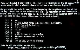
Pin 1 0v
Pin 2 Video output (sync continues when device is in standby!)
Pin 3 5.2v (expect 5v to 7v)
Pin 4 5.2v (ditto)
Pin 5 14.2v
Pin 6 -12v
Pin 7 4.8v when in use, 0v when in standby
Pin 8 Unknown (connected to the LED?)
Pin 9 0v
Pin 10 0v when in use, 2.4v when in standby
David Pilling, 10th May 2019, 23:08
| © 2019 Rick Murray |
This web page is licenced for your personal, private, non-commercial use only. No automated processing by advertising systems is permitted. RIPA notice: No consent is given for interception of page transmission. |