Rick's b.log - 2020/09/21
You are 3.148.106.49, pleased to meet you!
Rick's b.log - 2020/09/21 |
|
| It is the 24th of November 2024 You are 3.148.106.49, pleased to meet you! |
|
mailto: blog -at- heyrick -dot- eu
So I went and got that Tassimo Vivy 2 smart coffee maker that I purchased for €15 at the last vide grenier I went to before the end of the world.
Turning it over, it has some star shaped screws. Okay, just rummage a little deeper in my toolbox for the box of weird shaped screw attachments for my ratchet screwdriver.
Looking inside, we can see what makes the device work.
The blue and silver lump on the left, marked "CEM" is the pump. The long silver thing beside it is the heater. To the right of that, the controller board. Some plastic pipes for the internal plumbing and, well, that's about it.
Here is an annotated version to show the path of the water.
Now let's look at the parts in turn. The pump is a solenoid pump. It is actually "CEME", type E410. The coil power is 27W, achieving up to 2.8 bar pressure, with a maximum flow of 620 cc/min. As a solenoid style pump, it works by moving a plunger back and forth by a magnetic field. As the coffee maker claims to have variable flow rates (and certainly appears to with the dosette precharging), it is possible that it uses a transistor to modulate exactly how much of the mains passes to the pump, in a manner similar to how I observed my bread maker controlling its motor speed.
After the pump, the water (now at pressure) passes to the bottom of the heater, as you can see from this picture.
A the water has not been heated yet, there's an overflow system that returns water (if there's a blockage, heater scaled up, etc) back to the reservoir. You may just be able to see that there is a temperature sensor for the incoming water (so putting warm water in the reservoir for a hotter coffee won't work!).
The heater unit itself consists of two heater elements that run either side of a metal pipe. The elements get hot, and the heat is conducted through the metal to the water in the pipe. As long as the heater is carefully controlled (it requires knowing the rate of water passing as well as the temperatures of the incoming and outgoing water), it is an effective way of producing on-demand hot water.
At the top of the heater is another temperature sensor. There is also what looks like a small filter. This has an overflow pipe that deposits overflowed water into the side of the coffee machine 'head' (where it will flow down the red pipe at the front to be ejected out the bottom of the device (onto the bottom tray).
From there, the heat pressurised water is delivered to the head. This contains a mechanism that clamps the "T-Discs" down on to the little rubber thing that the water comes out of.
Inside the discs, dosettes, capsules, landfill... whatever you call them... inside the things the incoming hot water is forced around the outer edges of the disc. Small gaps allow the water to enter into the chamber, and the pressure forces the water to flow towards the centre of the disc. There, it either passes directly out (if a non-particulate mixture like hot chocolate or the various milk preparations used in the cappucino range) or through a fine plastic mesh filter if coffee granules or tea leaves. From that point, it passes down into the nozzle, falling into your cup.
There is one other little thing here, and it's part of what makes the Tassimo special. It is the barcode reader. Made by Zebra, a company with a lot of experience in barcode reading devices, it is a miniature fixed-position reader that is capable of reading the 2-of-5 barcodes printed on the dosettes in order to instruct the coffee maker all sorts of parameters about the preparation in question - the flow rate, the precharge, the temperature, the amount of water...
It is unlikely that any information on this device will exist. The first three letters of the code are "BSH", and if you recall that the Tassimo machines are made by Bosch, well, it seems clear that this is a custom device. It is also a sealed device, as you can see.
Which brings me to the final piece of the puzzle. The tiny motherboard. I have unclipped it in order to get a better photo.
Working top to bottom, it looks (black wire) that the heater might be the one controlled by modulating AC with a big transistor. In this case, the transistor connected to a big-ass heatsink.
Below the heatsink, that itty-bitty chip is a "VIPER06". It may well be this which is responsible for directly slicing apart the raw mains input in order to arrive at something akin to 5V for the electronics. If that's the case, then dealing with this thing would be a tad scary due to no electrical separation between the mains and the lower voltage parts. It looks like the (5V?) goes through some basic rectification, a choke, and smoothing before being fed into an ST LD33 which is a 3.3V voltage regulator.
The integrated circuit appears to be a standard STM32F030C8 System-on-Chip containing a 48MHz ARM Cortex-M0 core, 64KiB Flash, 8KiB SRAM, 6 16-bit timers (1 basic, 1 advanced, 5 regular), 2UARTs, 1 12 bit ADC with up to 10 input channels, up to 39 GPIOs, and being in a 48 pin LQF package, many of the pins can be configured as required. It actually seems a fairly powerful processor for a coffee maker. I think the one in my drone is simpler!
At the very bottom, nicely colour-coded inputs. The black one is to the water level sensor. The red one is the upper (hot side) temperature sensor. The white one is to the head closed switch. There's supposed to be some sort of solenoid to lock the head while brewing is in progress, so maybe the switch activates that too and it's a dual purpose cable? The blue one is to the lower (cold side) temperature sensor. Red hot and blue cold, get it?
The obvious elephant in the room is that bit to the lower right. Eight contacts with notches either side. There's a part of me that suspects this might be for factory programming the device. But, that said, it might turn out to have uses for us?
Knowing what the pinout is would require tracing each pin back to the SoC. Unfortunately as this coffee maker has never been used, I didn't want to strip it down completely, so I have no photos of the other side of the board. So all I can say at the moment is that it looks at if pin 1 (upper) is the 5V (or so?), pin 2 may be an optional complimentary 3.3V power supply (if two contacts on the board are bridged), pin 3 connects to the SoC's pin 31 which is PA10/USART1_RX/TIM1_CH2/TIM17_BKIN/I2C1_SDA. It would seem most likely that the actual purpose is USART1 RX. And if there's an RX (directly connected, so will be 3.3V TTL serial), then it suggests that a two-way communication with the device may be possible.
But, for now, I put it all back together.
Tassimo Vivy 2 teardown
As thunderstorms rolled in on Sunday, I wanted to do something outside so I could keep an eye on the weather (to unplug stuff if the storms got too close) but didn't fancy tackling weeds or bra......yes, that word.
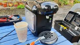
Tassimo Vivy 2 coffee maker.
Two screws on the bottom front, some on the bottom rear, and two on the side hidden where the water container goes. From there, it was a delicate job of easing the left side off little by little.
The water inlet is fitted to that half, you can open the unit up, but not remove the side completely.
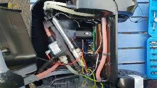
Tassimo Vivy 2 inside.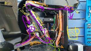
Tassimo Vivy 2 inside - annotated.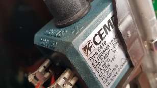
CEME pump.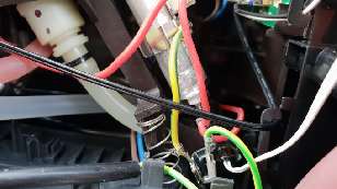
Pre-heater arrangement.
You can see here the two thermal cutouts. The black is connected to the top of the heater, while the red is common to the bottom of the heater and the pump. It's also interesting that it appears that the live is always connected (the far end of the red terminal looks like a brown wire that's the input AC live) and the neutral is switched. Okay, it doesn't really make much difference with AC, it just seems interesting that in order to reduce costs, they're using a method not unlike live chassis TVs from when I was young. This can be borne out by the fact that there's nothing inside that resembles a transformer.
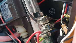
Heater and thermal cut-outs.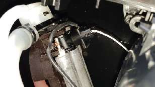
Top of heater unit.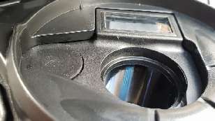
Coffee maker head.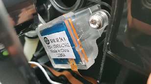
Tassimo barcode reader unit.
The ribbon cable carries seven lines. Obviously two are power. One may be a "read now" instruction to wake up the reader. And the other four? Perhaps two signals to indicate valid or invalid scan, along with a data and clock output? Or maybe I'm completely wrong and it just spits back serial and every other line is a ground plane? I'd need to take a good look at the motherboard to get a better idea of what's going on there.
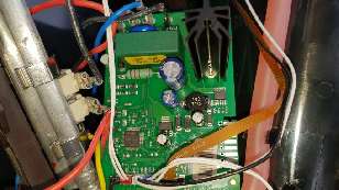
Tassimo Vivy 2 motherboard.
Next to it are the wires to the motor, perhaps passing through that big green box. "MBBC7 V5 EU FL" doesn't show up anything in Google, but I'm guessing it might be some sort of relay? It is made by E.I.S. Gmbh, a German company that produces electronics and circuit boards (in Bulgaria!) for their industrial partners. If you look at the extreme bottom right, you'll see E.I.S. are likely the ones who assemble these boards.
Finally, the ribbon connector for the barcode reader.
There are, as I said, eight contacts. This does not match any known ARM or ST-Link style connector. It would appear to be a custom style.
If I were to guess, I would say that the following would be present: 5V, 3.3V, GND, SWDIO, SWCLK, RST, UART1 TX, and UART1 RX. This would allow programming, and communication, with the device. Whether or not it would work now depends upon Bosch's level of paranoia and whether they ever intend for firmware updates to be possible. This is because the F0 devices can have a hardware bit set which disables (forevermore) the ability to use the debug interface.
Yes, before anybody tells me, I'm aware that it is often possible to bypass this by starting up in a certain way and glitching the power supply. Consider such things way beyond my skill set!
Rural problems: Bringing the bin back home
The cat emoji are because my bin has the address that the bin is associated with written on a big sticky label.
My bin's lock is rubbish
This one has a lot of speaking, and subtitles if you need them. Wait to see how long it takes me to flip the locked lid. At night!
John, 22nd September 2020, 09:29
It amuses me that the so-self-called cogniscenti seem to think that coffee made in such a machine is superior.
In fact, as an allergy sufferer, I know from my stomach migraines that they contain significant quantities of instant coffee.
Calling what they produce "coffee"is like calling the contents of a tin "fruit salad", or, worse, "fresh fruit salad"!
The contents of such a tin should always be referred to as "tinned fruit salad", but I don't really know what to call the contents of these pods.
So, in the same way one would apologetically say "It's only instant, I'm afraid!", when offering this stuff one should say "It's only out of a 'pod', I'm afraid!" to give fair warning.
Why the process of freeze-drying should be perfectly OK for red fruits, but produce toxins or allergens for coffee solutions I have no idea; but that's the way it is!
Ça y est !David Pilling, 22nd September 2020, 13:39
Probably you could run all the electronics from low voltage for testing or hacking.
Taking rubbish - in the UK they brought in the bin weighing tech. But there was outcry and AFAIK it has not been used.
Maybe you can say my coffee maker has a more powerful CPU than my first computer.David Pilling, 22nd September 2020, 13:41
STM micros websiteRick, 22nd September 2020, 14:13
Yeah, I saw the Viper chip blurb. Didn't understand any of the buzzwords. What's "vertical power", for instance?
They wanted to make the bins by weight here, but people complained. As I pointed out on my blog back when, which is worse for the environment - a bin full of cat litter (weighs heavy) or a bin full of polystyrene (very light)?
My first computer was a Beeb. The coffee maker is way more powerful than that ever was.Zerosquare, 22nd September 2020, 18:49
A parsing error :)
It's "[vertical] [power MOSFET]", not "[vertical power] [MOSFET]".
https://en.wikipedia.org/wiki/Power_MOSFETJohn, 22nd September 2020, 22:38
Electronics, I would have gone for thyristor - but then I'm old (fashioned)!John, 22nd September 2020, 22:40 Daniel, 1st March 2024, 09:04 Rick, 1st March 2024, 13:22
| © 2020 Rick Murray |
This web page is licenced for your personal, private, non-commercial use only. No automated processing by advertising systems is permitted. RIPA notice: No consent is given for interception of page transmission. |