The type of motors used within
RickBot
There are
two main types of direct current electric motor
in the world...
Standard
motors
The first type of motor is the
standard sort of motor where you apply a voltage and it
starts to turn. This type of motor only has two wires
coming out of it.
These are dead easy to interface.
Some transistors and/or relays to switch the power on
and off, and cater to current reversal to handle
'backwards'.
Unfortunately these motors suffer
because tolerances and rotational speeds (usually being
dependent on the applied voltage) provide no guarantee
that two motors will turn in the exact same
way. The effect of this would be 'wandering'.
Robotic
devices using standard motors come in two forms. Either
one motor drives both back wheels, and turning
is implemented by changing the angle(s) of the front
wheel(s). Or one motor controls one rear wheel and
sophisticated methods try to ensure that the device
doesn't wander... (or otherwise the designer says "to
hell with it" and allows for these intolerances in the
design).
Stepper
motors
The second type of motor is the sort
where to apply a voltage to the motor and it may turn a
fraction before 'freezing' in a fixed position. Usually
has four or five wires coming out of the motor.
These
are a lot more complicated to interface because they
work by alternating power to specific windings within
the motor in a specific sequence.
These motors
provide a fine degree of control. Each 'pulse' steps the
motor one time in the nominated direction. One step
could be something like 7.5º, so it'd take 48 steps to
turn full circle. As you have to explicitly step these
motors, assuming the loading doesn't stall the rotor,
you will always know exactly how much the motor has
moved, and it will be possible to keep everything in
perfect synchronisation for hours - of course,
practically every printer available from humble yet
noisy dot matrix models to freaky-smelling laser
printers use stepper motors for precise placement of the
paper and the print head (or laser beam).
A
disadvantage of stepper motors is that high torque
motors are a lot harder to come by than their standard
counterparts. For example, if battery life was no object
we could build a robot using two car starter
motors. These motors can turn an engine, so dragging
heavy stuff behind the 'bot shouldn't be too hard. Now,
where would I easily obtain stepper motors
larger than those used within photocopiers and the
like?
Now for another advantage - applying a fixed
current to a fixed part of the coil will 'lock' the
motor. This feature could be used as a crude form of
'brake'.
And... another advantage. Because we move
the motor in steps, our chosen stepping rate will
directly affect the speed. To do this with a
standard motor requires pulse width modulation. Not so
different, but less precise.
A further complication
of stepper motors
Many types of this motor
exist, such as the delta configuration. We shall not
concern ourselves with this, because it is like saying
the Wankel engine exists ... it does, but how
many people in school mechanics class have actually
every seen one in real life, as opposed to a
diagram in a book or a little model.
There are two
main types of stepper motor and each have plus points
and minus points.
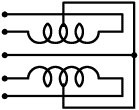
The first type of stepper motor
is the unipolar design, where the four
'poles' are two windings which are centre-tapped. The
centre tap is usually connected to the +ve supply
and we ground the required parts of the windings to
energise them and set up magnetic currents. By switching
which poles are magnetised, you can cause the motor to
turn. Reverse the direction of the stepping, the motor
turns the other way.
Here is a schematic
representation of this type of motor:
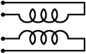
The second type of stepper motor
is the bipolar design, which is similar to the
above with two windings, only without the
centre tap. This means you can wind the motor core in a
more efficient way. A bipolar motor built on the same
frame as a unipolar motor will deliver 35%-45% higher
torque. The big complication is that these motors
require polarity adjustment. Let's say coil #1 requires
+ve on the left and -ve on the right to turn clockwise a
step. Well, to go counter clockwise we'd need to apply
-ve to the left and +ve on the right. This is usually
achieved by a design known as an 'H bridge'
(actually, most cheat and use and IC!) to flip the
polarity as required.
Here is a schematic
diagram:
What type of motor do we
use?
Within
RickBot, we shall be using two
unipolar motors with a 7.5º step angle. This is
purely because it is what I happened to salvage from an
old printer. In any case, the outputs from the
Amélie board are identical: left motor
direction, left motor step, right motor direction, right
motor step. It is possible to drive either type of
stepper motor from this.
As it stands, the application
code uses Timer2 to generate interrupts after the
desired time interval has passed, to control the motor
stepping. You could try hooking the
step signal through a power transistor to
directly switch a standard motor if you'd prefer to use
one of
those.