It is the 1861st of March 2020 (aka the 4th of April 2025)
You are 3.128.199.58,
pleased to meet you!
mailto:blog-at-heyrick-dot-eu
Geekfest! An OLED on the Pi! (part 1)
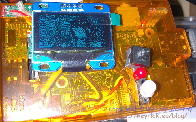
An OLED. It's a sort of display. Based upon organic light emitting elements, it consumes very little current (all pixels lit, maximum brightness = 36.2mA; all pixels lit, minimum brightness = 13.7mA) and gives a remarkably high contrast display. This is because the elements themselves emit colour. In a conventional display, there is a backlight and the pixels alter how much backlight shows through (a side effect being you never get a truly dark black). With OLED, there is no backlight. Black is absolute. Additionally, as the elements emit light, there is no weird light-twisting and polarisation going on. As a result of this, the OLED can be seen from extreme angles; although display devices are much better these days than in the past. The photo above was taken with a mobile phone, firing a flash about six inches away, yet even like that the display can still be seen.
This particular OLED - which can be bought for about €12-€15 from Hong Kong (look on eBay) - offers 128×64 resolution in "on" and "off". While that is only 8,192 pixels in total, it is enough for a status display.
When you look for a display, there are several criteria that you must keep in mind:
It must work directly off of 3.3V (5V is not acceptable).
It must support an IIC interface (not SPI).
It must be 128×64.
The controller chip must be an SSD1306 (most are).
You must be using a RaspberryPi. The IIC bus on OMAP devices (Beagle, Panda...) is 1.8V. Not compatible.
Even with these limitations, there are a number of options. White ones, blue ones, blue/yellow ones... that are either 1.3" (as mine is) or a smaller 0.96". They're really cheap, so why not take a look?
Now here's the complication. Sadly, it may be a dealbreaker for some. It isn't hard, it is just incredibly fiddly.
You may need to modify your OLED in order to get it to work.
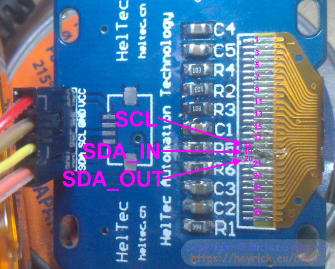
It seems for some unknown reason that the driver chip inside the OLED has separate pins for SDA (that's IIC data) input and output. They are not normally joined. Now this is no big deal for a microcontroller (a PIC or Arduino) where a bit of custom code can bit-bang IIC data; however for us this is a massive deal. Without an SDA output, the RISC OS IIC system will never see ACK bits, so it will believe that transmission has failed. Therefore, we need to join SDA_IN and SDA_OUT.
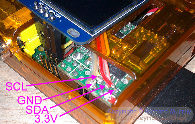
First up, here's a picture of the back of the display, with the modification having been done:
Firstly: With a multimeter, count to line #18 on the ribbon connector and verify that it is connected to the pin on the header marked SCL - that's the yellow wire on the left of the photo.
Then verify that line #19 is connected to the SDA pin on the header - that's the orange wire on the left.
If your display is different, give up. You can try connecting it, see if it works...
Now with the multimeter, test if line #20 is also connected to SDA. If it is, you're in luck. Nothing needs to be done.
Now check if line #20 is connected to GND. If it is not, then you only modification is to 'short' lines #19 and #20 with a delicate wipe of a fine soldering iron to smear the solder between the two. Check with a multimeter that all is correct (lines #19 and #20 go to SDA, line #18 to SCL, line #21 probably grounded), then you're done.
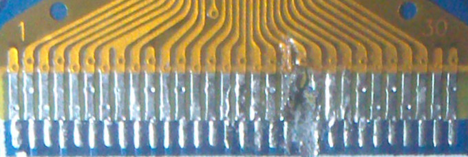
In my case, I was really unlucky and line #20 was grounded (what the hell, guys?). So I needed to use a blade to cut away the track of the ribbon connector, lift it up (without breaking it), scrape away all of the circuit track underneath to break the ground connection, and then fold it over itself and solder it to line #19. Conceptually simple, somewhat harder in practice.
Gory-close-up time:
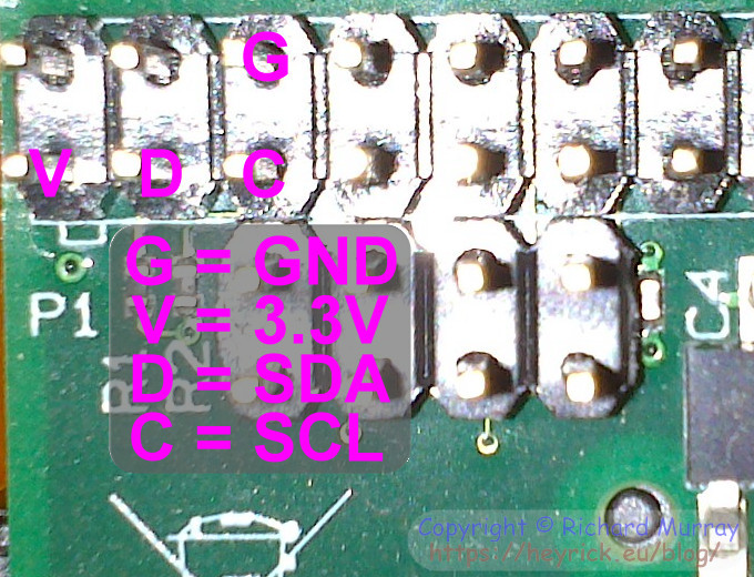
That part done, the next part is wiring it up to your Pi. This is easy. There are only four wires - 3.3V, GND, SCL, and SDA.
If you have a bare Pi, then the wiring is like this:
You ought to be able to hook it up with a few wires that have header plugs at each end.
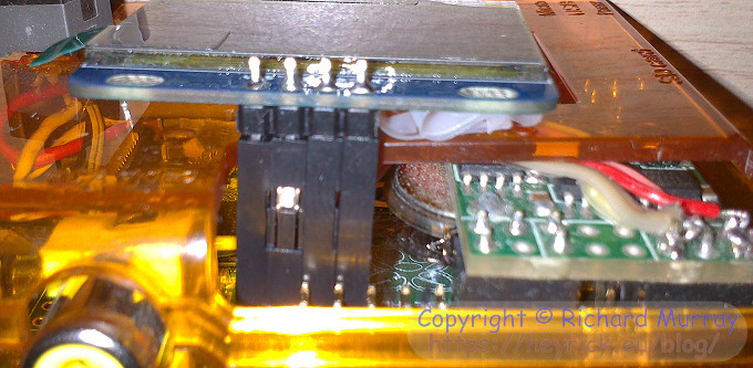
In my case, I had a CJE RTC module already fitted, so I soldered a short piece of ribbon wire to the appropriate locations:
Here it is, looking from behind. You can see the display is held in place with a little rolled up piece of sellotape. It is also worth mentioning that, in this orientation (in order to get the pins to go tidily in through the Pi's casing), we are mounting the OLED upside down. The driver module is written with the expectation that your OLED will be upside down as well - however this can be changed in the initialisation call if you mount yours the right way up.
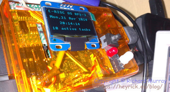
And, finally, this is what I can look up and see when my Pi is running but I don't have the screen on:
Again, flash photography, no difficulties in seeing the display. That's at the default 50% brightness, too.
I have a driver module, but I am not releasing it yet. It is all ready (except for a few tweaks), the problem is I do not yet have an official allocation for the SWI chunk and error block. The module, as it stands now, uses exactly the same SWI chunk as the MIDI module (thus the two could not sensibly co-exist) because, to be honest, I based my CMHG definition on the one I'd already written for the MIDI module. I expect to have an allocation in a few days, it is Easter after all. Then I can talk about programming the OLED display.
Until then, take a look at this for an idea of the capabilities:
It's a simple demo program written in BASIC. It will be supplied along with the driver module so you can pick it apart.
Your comments:
Please note that while I check this page every so often, I am not able to control what users write; therefore I disclaim all liability for unpleasant and/or infringing and/or defamatory material. Undesired content will be removed as soon as it is noticed. By leaving a comment, you agree not to post material that is illegal or in bad taste, and you should be aware that the time and your IP address are both recorded, should it be necessary to find out who you are. Oh, and don't bother trying to inline HTML. I'm not that stupid! ☺ As of February 2025, commenting is no longer available to UK residents, following the implementation of the vague and overly broad Online Safety Act. You must tick the box below to verify that you are not a UK resident, and you expressly agree if you are in fact a UK resident that you will indemnify me (Richard Murray), as well as the person maintaining my site (Rob O'Donnell), the hosting providers, and so on. It's a shitty law, complain to your MP. It's not that I don't want to hear from my British friends, it's because your country makes stupid laws.
You can now follow comment additions with the comment RSS feed. This is distinct from the b.log RSS feed, so you can subscribe to one or both as you wish.
youyoudeyou, 19th July 2014, 12:09
very interesting! could you share the library and programme? cause I have same hardware (Raspi+HuiTec 128*64 OLED), but I didn't know how to build it up....
This web page is licenced for your personal, private, non-commercial use only. No automated processing by advertising systems is permitted.
RIPA notice: No consent is given for interception of page transmission.