It is the 1876th of March 2020 (aka the 19th of April 2025)
You are 18.117.71.21,
pleased to meet you!
mailto:blog-at-heyrick-dot-eu
How to use an oscilloscope
What is an oscilloscope?
An oscilloscope is an important piece of test equipment. Its function is simple - to take an electrical input and show you what it looks like. While this might sound boring, all sorts of problems can be diagnosed by simply seeing the signal. If it is supposed to be flipping at a specific frequency, is it? Is it missing anything? Are there disturbances (noise) in the signal that is being mistaken for data or triggering things at the wrong time? For a complex signal, such as a PAL television signal, you can see distinctive parts of the signal waveform, and then trace parts of it through the circuitry of a television as parts (field sync, line sync, colour burst, luminance...) are extracted and dealt with.
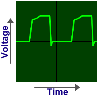
At its most basic level, the oscilloscope plots on its screen the input signal against time. The signal affects the up and down motion of a dot on the screen, and the time setting moves the dot from left to right.
Types of oscilloscope
Basically, there are two types of oscilloscope. The analogue (cathode ray) type, and the digital type.
Analogue oscilloscopes are simpler to use, offer fewer fancy features (such as signal analysis and interpretation), tend to be cheaper than equivalent digital models, and provide a proper real-time display of input signals. Analogue oscilloscopes are best when dealing with real life analogue inputs or slower digital signals. Analogue oscilloscopes work by amplifying the input signal as necessary to cause the dot to move up and down the screen. As such, there is no issue of sampling resolution or data points, as it is analogue, and thus capable of the near infinite degrees of resolution offered by nature and physics themselves.
On the converse, a digital oscilloscope will typically offer features such as the ability to capture erratic one-off signals (something that is practically impossible on an analogue model), zoom in to examine complex waveforms, save the waveform, print it, etc etc.
However, note that the display of a digital oscilloscope is sampled, processed, and then regurgitated so there is the problem that you may not be seeing what is really happening. If you measure a 20MHz signal on a 20MHz digital oscilloscope, you will be driving it at the end of its capabilities and there may be too few sample points (or too few per time domain) to show you that signal correctly - generally speaking it won't look anything like the same 20MHz signal as measured by a 100MHz oscilloscopes. In principle the effective range of an oscilloscope is half the maximum sampling speed of the acquisition system due to the Nyquist limit; however for proper undistorted signals, you ideally need an oscilloscope with a sampling rate four or five times greater than the maximum rate of the signal you want to examine. This is why you sometimes see insane speeds for digital oscilloscopes; a 100MHz model is best for 20-25MHz, and so on.
Add to that, many typical oscilloscopes have an 8 bit sampling resolution (256 discrete 'levels'). Those with greater resolution are considered "high accuracy", did you hear the "kerching!" sound as you read that? To put that starkly into context, the output from a CD is a 16 bit stereo signal. The audio waveform can use up to 65536 discrete levels. Thus, how can you accurately observe something as simple and commonplace as that which is present on the headphone jack of any CD player (or MP3 player, for that matter) when the oscilloscope itself isn't capable of that level of accuracy?
In the old days, there was a distinct lag between a signal happening and a digital oscilloscope showing it. This is less of a problem these days with ingenious contraptions such as the "digital phosphor" (I believe this is a Tektronic invention?) which can display a real-time trace. How this works is by having dual acquisition systems. One samples the signal and spits it directly to the screen as fast as possible, the other samples the signal at a better resolution and stores it in memory for the other functionality.
You will notice there is a lot of text about digital models, not so much about analogue. This is because digital oscilloscopes have some important technical caveats, and because analogue oscilloscopes are just inherently simpler.
The parts of an oscilloscope
Here, we are going to discuss a fairly basic analogue oscilloscope, such as would be found in schools and the workbenches of geeks that don't do much electronics work (so can often pick up an ex-school model for a good price). The basic principles apply equally to digital oscilloscopes.
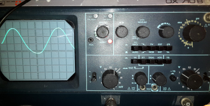
Let's first look at the oscilloscope:
My oscilloscope's specifications are as follows:
Dual trace capable of 15MHz input (or 10MHz for the 10V/20V ranges) with a sensitivity level of 5mV/square.
A useful range of automatic triggers, plus a TV triggering that triggers on each field sync.
The timing mechanism covers a range of 0.2s/square down to 0.2µs/square, with a precision of ±5%.
1 megaohm / 35 picoFarad inputs, capable of handling up to 400V in both AC and AC/DC modes. This means a suitable ÷10 probe should permit measurements up to 4kV, which may be of more use to television repairmen of the older generation.
A range of options of what to do with the two input signals (YA, YB, YA+YB, YA and YB, XY).
Clear and simple controls.
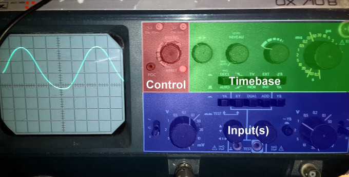
The oscilloscope is essentially broken down into four important parts, which are shown in this annotated diagram:
The most important part is the graticuled display. What this means is the display which contains a grid. This is either printed on an transparent overlay or etched onto the glass (analogue) or inserted by software (digital).
Typically you should expect to see eight squares vertically, and ten horizontally, with the central markers usually containing dashes to further subdivide the square into five sections along each axis, as can be seen from the pictures above.
Now something that is critical to understand is that all of the other controls are relative to the squares of the graticule. For example, if your timebase is set to 1 millisecond, that means that each division (square) horizontally represents one millisecond of time. Accordingly, it will take 10ms to traverse the entire screen.
The controls are for turning the oscilloscope on and off and setting it up.
The timebase is the most complicated part of the entire device. Ostensibly it will make the trace pass from the left to the right at a predefined speed, however pretty much every oscilloscope will offer a range of "trigger" options in addition to simply free-running. This can make it easier to see certain types of signal.
The input completes the puzzle, by taking a signal and using it to move the trace up and down. As with the timebase, each option represents one square so if your voltage selection is set to 0.5V per division (square) vertically then you will be able to see 4V on the screen, which can just as easily be -2V to +2V. There should be a knob to allow selection of AC or DC waveforms, plus one to move the trace up and down the screen so you can set the 'zero' point. For instance, if you are measuring DC signals you could set the bottom line on the screen to be the 0V position as the signal shouldn't go below 0V.
Let's look at these in more detail...
Controls
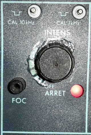
On analogue models, the on/off control is frequently coupled with a brightness control in much the same way as older televisions used to have the power and speaker volume on the same knob. This is necessary as the faster speeds traverse the screen more and more rapidly which mean the trace becomes dimmer and dimmer. The brightness control can be used to compensate for this.
The tube focus is not locked as it is on a TV, so may need adjustment depending on the temperature of the cathode ray tube.
Finally, there may be one or two test points that provide a square wave at a known frequency. This is intended to be used for calibrating test probes.
Timebase
The timebase has two modes it can run in. Free running, or triggered. When free running, the controls select what speed the trace sweeps from left to right, and this will happen continuously. In triggered, a variety of options determine how and when to trigger and the oscilloscope will sweep the trace once (at the defined speed) per trigger. Of note is that when in triggered mode, nothing will appear when there is no trigger input.
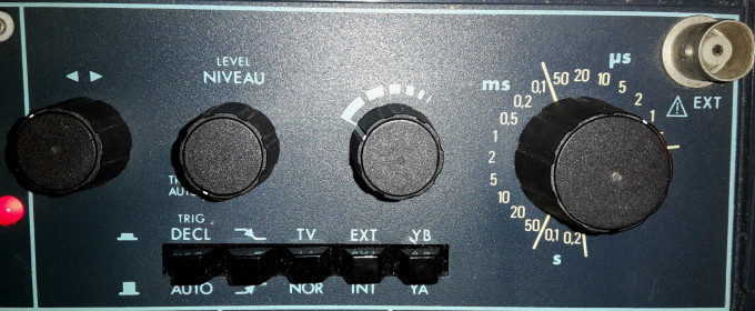
From left to right. The knob with the two arrows above is is for adjusting the horizontal position of the trace. Note that this is purely for aligning the trace on the screen, it does not permit you to choose other parts of the waveform.
The Level knob (Niveau in French) is to control when the triggering happens, if using one of the triggering modes. Think of it as a sensitivity adjustment.
The next knob, with the dashed lines, is for tweaking the timebase selection. In its leftmost position (as shown), the sweep will be at the indicated speed. As the knob is turned to the right, the speed will increase until it is nearly the speed of the next faster timebase setting. This may be useful when you are not interested in the time, but wish to have a specific waveform fill the display for closer examination.
Finally, we get to the timebase speed control. Broken into seconds, milliseconds, and microseconds, each option on this control (in the absence of the stretching control just described) corresponds to one horizontal division of the screen. The left-most setting, for example, is 2 milliseconds. This means each square across the screen represents 2 milliseconds, or 10ms for a sweep across the entire display.
To convert milliseconds to Hz, you should divide a thousand by the indicated time. For the 2 millisecond, that would be 1000÷2, which is 500Hz per division. If your waveform spans two divisions (such as a sine wave might), that would than be 500Hz÷2, or a 250Hz signal.
50ms is 20Hz; 1ms is 1kHz, 0.1ms is 10kHz, 50µs is 20kHz, 1µs is 1MHz, 0.5µs is 2MHz. Per division.
Using this, we can see that our timebase is on the 5µs range (200000Hz per division), and the waveform takes just over 6 divisions across the screen. Thus 200000÷6.1 gives us an estimated frequency of 32786Hz. Which is about right, as it is actually a 32.768kHz timing crystal from a clock. I was surprised to see a timing crystal giving a perfect sine wave, I had expected a square wave or somesuch.
Triggering modes
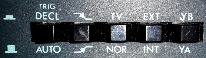
Automatic mode (leftmost button, out) means the trace continually sweeps across the display. With this button pressed in (Déclenché in French), triggered mode is engaged.
The second button selects to trigger on the rising edge (out) or falling edge (in) of the input.
The third button selects normal triggering (out) or a special TV mode (in) which will auto-trigger on every line sync.
The fourth button selects between internal triggering (out) or triggering by an external signal (in), the external signal being connected to the BNC socket on the upper right.
The final button selects whether the first input 'YA' (out) or the second input 'YB' (in) activates the triggering.
Normal continual-sweep use is achieved with all buttons in their out positions.
Input
These are the controls for an input signal. The signal is connected to a BNC socket just below the input controls, you can see this on the topmost picture.
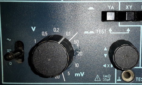
The knob on the left selects between AC component (the wavy line), DC and AC (straight line and wavy line), and 0V. Normal operation is DC/AC mode. The AC option can be useful for observing an AC carrier on a DC signal (by separating out the AC part). The 0V option is useful to set the 0V reference point.
As with the timebase, the voltage selection (running from 5mV to 20V) represents the voltage per division. You can see the control is set to 0.1V per division, and the signal in the topmost picture spans a little over 3 squares vertically; which means that it is 0.3V peak to peak.
The knob with the up and down arrows adjusts the horizontal position of the trace. For an AC signal, it is common to place the 0V on the centre line.
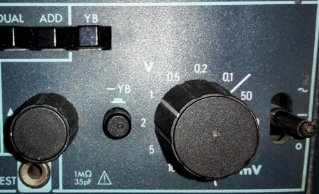
The second input controls are very similar to the first, with the addition of a button (marked -YB) which can invert the signal.
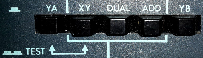
The first button (YA) pressed in selects to display the YA input on the display.
The second button (XY) pressed selects to have YA control the horizontal position and YB control the vertical position (and the timebase is not used). If both of the two leftmost buttons are pressed, a special test mode is engaged. This will be described another time.
The third button (DUAL) pressed selects to display both inputs on the display as individual traces.
The fourth button (ADD) pressed selects to add the inputs together and display a single composite trace on the screen.
The fifth button (YB) pressed selects to display the YB input on the display.
Dual trace?
It is worth pointing out that most dual trace analogue oscilloscopes do not have dual traces inside the cathode ray tube. The way two traces are actually displayed is by using some trickery.
For the slower timebase settings (0.2s to 5ms on my model), the dual traces are created by rapidly switching from one position to the other as the trace passes across the display. By flipping back and forth, the illusion is of two traces on screen at one time.
For the faster timebase settings (2ms to 0.5µs on my model), the dual traces are created by displaying one trace, then the other, alternately. While this technically means that the oscilloscope is only actually showing you every other sweep, in practice it does not matter as the entire period for sweeping the two traces is 4ms, or 1/250th of a second - far faster than the eye is able to see. Faster indeed, than any domestic video camera stands a hope of seeing.
Using the oscilloscope
For viewing a single trace:
Set the left/right and up/down arrow controls to their middle positions.
Set the timebase to internal automatic sweep (non-triggered), at around 1ms/sec (the actual speed doesn't matter, it's so something appears on-screen).
Set the AC/DC-AC/0 knob(s) to the 0 position.
Press either the YA or YB button (if necessary) to select which input to view.
Switch the oscilloscope on.
Wait a few moments for the device to warm up.
Adjust the brightness and focus as necessary to provide a sharp and clear trace across the screen.
Use the left/right arrow control to centre the trace horizontally.
Use the up/down arrow for the appropriate input to at the vertical position of the 0V. For an AC signal, it is typical to place 0V in the centre of the display. For a DC signal, it is typical to place the 0V towards the bottom.
Set the AC/DC-AC/0 knob to either AC or DC/AC as appropriate (select DC/AC if you aren't sure).
Set the input voltage selection to the maximum setting, 20V/division. Never connect an unknown input with the oscilloscope set to its most sensitive setting - you risk damaging it!
Apply the input signal. Either by touching the probe to the circuit under test if it is safe to do so, or if the probe is already hooked to part of the circuit, by plugging the probe in by the BNC plug.
Adjust the voltage control until you have a signal that spans between two and six squares vertically (as appropriate for the input).
If you wish to use a triggered sweep, select the type of triggering now.
Finally, adjust the timebase for the desired sweep time appropriate for the signal you are looking at.
Dual trace:
Essentially as above, but when you would select YA or YB, you would instead choose DUAL for both inputs visible side by side, or ADD to merge the two inputs.
In DUAL mode, you may find it helpful to adjust the vertical positions of the traces (up/down arrow controls) to place one trace in the top half of the screen, and the other trace in the lower half. Digital oscilloscopes can offer more assistance here by giving the traces different colours allowing them to appear on top of each other and still remain distinct.
Remember, you can set the voltage differently for each input.
XY mode:
Choose the XY button. This disables the timebase and sets up the following:
The YA input controls the vertical placement.
The YB input controls the horizontal placement.
Be careful not to run the oscilloscope with no input in XY mode, as the result will be a single dot on the screen which could damage the screen.
Your comments:
Please note that while I check this page every so often, I am not able to control what users write; therefore I disclaim all liability for unpleasant and/or infringing and/or defamatory material. Undesired content will be removed as soon as it is noticed. By leaving a comment, you agree not to post material that is illegal or in bad taste, and you should be aware that the time and your IP address are both recorded, should it be necessary to find out who you are. Oh, and don't bother trying to inline HTML. I'm not that stupid! ☺ As of February 2025, commenting is no longer available to UK residents, following the implementation of the vague and overly broad Online Safety Act. You must tick the box below to verify that you are not a UK resident, and you expressly agree if you are in fact a UK resident that you will indemnify me (Richard Murray), as well as the person maintaining my site (Rob O'Donnell), the hosting providers, and so on. It's a shitty law, complain to your MP. It's not that I don't want to hear from my British friends, it's because your country makes stupid laws.
You can now follow comment additions with the comment RSS feed. This is distinct from the b.log RSS feed, so you can subscribe to one or both as you wish.
David Pilling, 16th January 2016, 18:29
printf for electronic engineers
Bear in mind that usually the inputs will not be floating but referenced to mains earth, e.g. connecting USB +5 V to the low side of your 'scope input, will form a short circuit.
Similar fun if you use your 'scope on the mains supply.
Rick, 16th January 2016, 22:08
printf() for electronic engineers. I like that.
Yes, two things I know never to do with oscilloscopes: 1, never connect them to the mains. It is possible with isolating transformers and such, but one really needs to know what they are doing. 2, it is not, and should never EVER be used as an ECG. It is potentially risky with battery powered digital models, trying to monitor a heart by probing with a mains powered analogue 'scope that has the shield side of the wire pegged to mains earth is a special sort of stupid. There is a reason medical ECGs are hideously expensive (designed not to fry the person being tested), and those cheap heart monitors available on eBay for a tenner use infra-red sensors to detect the pulse in a finger (no electrical contact). Milliamps across the heart? That's what a defibrillator does, and we all know what those are used for... 2b, related - it's not a brain wave probe either...
Zerosquare, 17th January 2016, 23:21
"1 megaohm / 35 picoFarad inputs, capable of handling up to 400V in both AC and AC/DC modes. This means a suitable �10 probe should permit measurements up to 4kV, which may be of more use to television repairmen of the older generation." Don't try that with a standard �10 probe, this is dangerous; you need a special high-voltage probe. But, as you mentioned above, if you're doing this kind of stuff, you better know exactly what you're doing.
David Pilling, 18th January 2016, 02:44
'scope as ECG - would not work - far too much noise. ECG has to have a lot of filtering to take out 50/60 Hz.
David Pilling, 18th January 2016, 18:26
Here on the web, where fools may be watching, we say "all contact with electricity is deadly and must be avoided". Meanwhile back then, Physics teacher used to get us all to join hands, and connect us up to high voltage. I'd avoid connecting myself to mains powered, full of very high voltages old fashioned scope, but then again you will almost certainly touch the inputs whilst using it.
Rick, 19th January 2016, 20:17
Voltage doesn't kill. Anybody who has played with a Van de Graff generator has held on to potentially hundreds of thousands of volts. If you're unlucky and the kid beside you was a bastard, then the sum total of all that charge would make a very tiny spark. Which can easily pass through the fabric of a school uniform to afflict, shall we say...more sensitive parts of the body... By contrast, the mains at a mere 230V (EU) or 110V (US) [other places may vary] is enough to kill a group of people holding hands stone dead. How? It's the CURRENT. A few milliamps around the heart and you're screwed. A mere 10mA can cause a severe shock. Above about 50mA and you become a corpse. A decent trip switch will kick in at 35mA so you'll learn not to do that ever ever again, but should survive. Should. Sometimes they just aren't quick enough.
Rick, 19th January 2016, 20:22
I should point out that it is specifically worse with the mains. You can (usually - with dry hands) touch the contacts of a car battery (which can deliver up to hundreds of amps) without instantly vaporising. But you absolutely cannot do the same thing with the mains, for two reasons. The first is the higher voltage coupled with higher current is capable of penetrating deeper into the skin. The battery is low voltage, the Van de Graff is low current. The mains? Like the worst of both. And secondly, the mains is AC. This means it switches polarity fifty (or sixty) times every second. Imagine being smacked in the face with a claw hammer. Now imagine being smacked in the face with a claw hammer fifty times a second. That's what the mains is like to your body...
(ps: ouch)
Rick, 19th January 2016, 20:35
Boring disclaimer - don't try this at home, use at your own risk, your home may be at risk if you don't keep up repayments on a mortgage or other loans secured on it, serving suggestion only, actual contents may vary, contents may be hot, may contain peanut, not to be taken orally, not dishwasher safe, not intended to be used in medical applications, not suitable for pregnant women.
This web page is licenced for your personal, private, non-commercial use only. No automated processing by advertising systems is permitted.
RIPA notice: No consent is given for interception of page transmission.