Rick's b.log - entry 2023/01/14 |
| ||||||
mailto: blog -at- heyrick -dot- eu
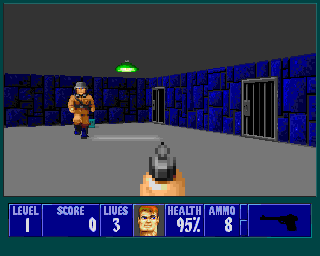
Basic ray castingFor many years I have wanted to understand how ray casting works. That is to say, the sort of world building as used in games such as Wolfenstein, Doom, and so on.However, a combination of dyscalculia (that's messing up numbers) and a lack of time to get around to thinking about it meant that decades passed by and nothing got done. Until today.
I suppose one of the main hindances, sadly, was a series of articles back in the Spring and Summer of 1997 in Acorn User called "Virtuality" that repeated endlessly that the whole thing was "complicated" and that one should contact the author if more explanations were required.
Unfortunately, all of that was complete bollocks. It is actually surprisingly simple. The core code for a very simple raycaster can fit into a screenful or two.
So what I am going to present you with today is what the Acorn User article should have started with - a simple BASIC program that will perform the rendering. It may take somewhere between eight and thirty centiseconds to draw a screen (meaning something between 3fps and maybe 12fps, purely for the drawing). Slow, yes. Too slow for making a game with. But on the other hand you'll get to understand how it actually works. Once you understand what's going on, then (and only then) should redraw speed and optimisations become a concern.
What follows is pure simple BBC BASIC. Not a single line of assembler in sight. It'll work on anything from a RiscPC onwards.
This code and the method is based upon that presented by Lode Vandevenne. The reason for choosing this is because it works rather differently to most other raycasters in directly using vectors instead of maintaining the direction as an angle and converting. For some reason, this has led to a method and corresponding source that is delightfully succinct. It does suffer in that it requires a competent floating point unit, so you might not want to write this in C just yet if you have the DDE. To ram home the point, here is a screenshot of a squished version of the entire program. Okay, fair enough, I've used a small font size. But it's still readable and it... is actually really compact. 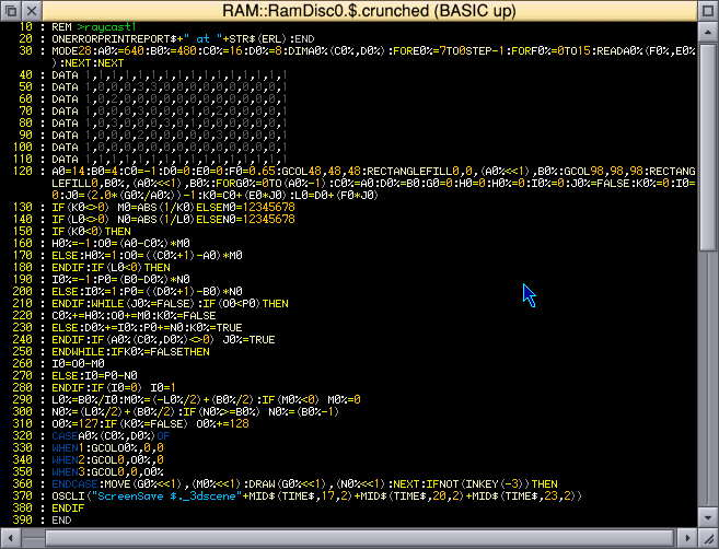 The entire program - yes, this is it, all of it.
What is ray casting?Ray casting is the ability to draw a world that looks three dimensional. For the purposes of this demonstration, we shall be drawing this: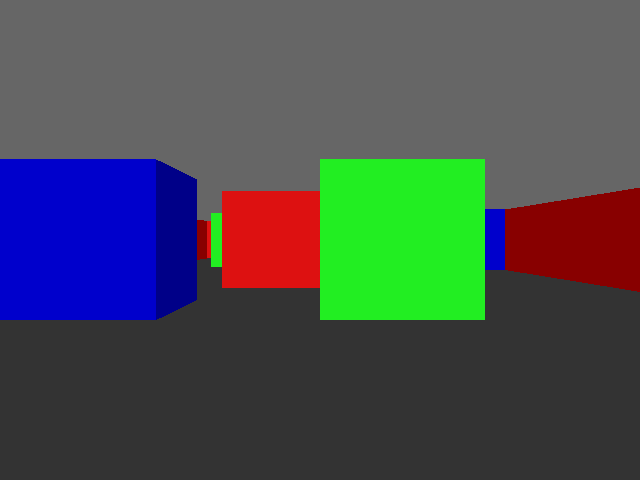 Our colourful world. But before I look at what ray casting is, we must first look at ray tracing.
So, what is ray tracing?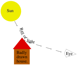 In science class you should (!) have learned a little about how we see things. Rays of light come from a light source, such as a bulb or the sun, and bounce off of objects. These rays of light then enter our eyes where we perceive them, as demonstrated by the naff drawing on the right. In science class you should (!) have learned a little about how we see things. Rays of light come from a light source, such as a bulb or the sun, and bounce off of objects. These rays of light then enter our eyes where we perceive them, as demonstrated by the naff drawing on the right.
More advanced science will tell you that there's no such thing as a 'ray', it's a never-ending stream of photons. It also will have explained that we see in colour because (whitish) daylight contains all sorts of different colours all mixed together. We see grass as green because the blue, red, yellow, etc are all absorbed, and green is reflected. So it's the green that we see. And so on.
Ray tracing is the manner of faking this in a computer. Since trying to calculate what comes from all of the possible light sources in the virtual world into the virtual eyeball would take until the heat death of the universe, it instead performs the calculation backwards.
So, then, what's ray casting?In order to create a full 3D-style animation, it takes powerful computers a lot of time. Older productions such as the movie Toy Story were generated using render farms. That is a whole pile of computers (117, in that case) churning out the frames that make up the movie, one by one. Depending on the complexity of the frames, the fastest were done in about 45 minutes. The more complex took over a day. Per frame. Of course, this was done back in 1998-1999 when computers were a fair bit slower.Ironically, the render time of the latest Toy Story film was about the same. The more modern computers are a lot more capable, but this didn't translate into quicker render times, it translated into more complex imagery. Clearly, for a simple game such as the likes of Wolfenstein, waiting for frames to render would not be a particularly immersive experience. You see a Nazi soldier, you mash the fire button, then you go make a cup of tea while the computer churns through the animation of that happening. Uh, no, just no. What ray casting does is epic cheating. As you know, a screen is made up of pixels in two dimensions. There's horizontal, across the screen, and there's the vertical up and down. The beginning of The Twilight Zone would have made that part quite clear. ☺ Instead of attempting to work out the value of every single pixel on the screen, what ray casting does is to split the screen into a set of vertical strips. That is to say, columns going from left to right across the screen. If I blank out every other column, you can see what I mean... 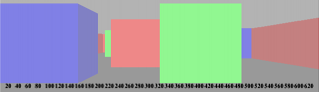 Drawing the world in vertical slices. For each screen column, two rays are "cast out". That's a weird expression, because to me being cast out is like "away with you, and never darken my doorstep again", but I'm not the one who named it. Anyway, two rays are cast out for every column across the screen. These rays travel together (I'll explain why two shortly) and they move out from the viewer's position until something is hit. When something is hit, this gives us a reference in our "map", which tells us three things. What was hit, what side of it, and how far away it is.
Knowing what was hit allows us to know what colour (or texture) we should use to draw the object. And knowing how far away it is allows us to know how big to draw it.
Wait, you said there are two rays?Yes. But to understand why, we first need to look at what's actually going on. So, let's backtrack a little.
FIRST, KNOW THISWe are working strictly in two dimensions.Let me repeat that.
WE ARE WORKING IN TWO DIMENSIONS.
That we end up with something that looks sort of 3D on the screen is great, but that illusion is the only part of this entire process that is in any way three dimensional. We have a map, of so many elements across, and so many up and down. This map will be filled with numbers. A zero represents nothing, an empty square. Non-zero means there's a wall block there. The number can relate to colour, texture, or what-have-you. We use floating point (that is, numbers with fractional parts) because the viewer position and the rays do not jump from one element to the next. There's a lot more finesse than that. So the viewer position may well be "four and two fifths". That's perfectly fine.
But when we are working our way around the map, we are going left and right and/or up and down in the array. This will make a little more sense once you've seen the map (it's just below), but keep in mind at all times that everything that happens is two dimensional.
The mapThe map is a simple array. In our example, it is built up as follows:REM The size of the 2D map
REM Let's keep it simple for now
mapx% = 16
mapy% = 8
DIM map%(mapx%, mapy%)
FOR loopy% = 7 TO 0 STEP -1
FOR loopx% = 0 TO 15
READ map%(loopx%, loopy%)
NEXT
NEXT
REM 0 = Empty
REM 1 = Red square
REM 2 = Green square
REM 3 = Blue square
DATA 1,1,1,1,1,1,1,1,1,1,1,1,1,1,1,1
DATA 1,0,0,0,3,3,0,0,0,0,0,0,0,0,0,1
DATA 1,0,2,0,0,0,0,0,0,0,0,0,0,0,0,1
DATA 1,0,0,0,3,0,0,0,1,0,2,0,0,0,0,1
DATA 1,0,3,0,0,0,3,0,1,0,0,0,0,0,0,1
DATA 1,0,0,0,2,0,0,0,0,0,3,0,0,0,0,1
DATA 1,0,0,0,0,0,0,0,0,0,0,0,0,0,0,1
DATA 1,1,1,1,1,1,1,1,1,1,1,1,1,1,1,1
REM /|\
REM |
REM Viewer is here, fourth row up. looking to the LEFT.
That means the map looks like this, with the viewer's location in blue. 1 1 1 1 1 1 1 1 1 1 1 1 1 1 1 1
1 0 0 0 3 3 0 0 0 0 0 0 0 0 0 1
1 0 2 0 0 0 0 0 0 0 0 0 0 0 0 1
1 0 0 0 3 0 0 0 1 0 2 0 0 0 0 1
V
1 0 3 0 0 0 3 0 1 0 0 0 0 0 0 1
1 0 0 0 2 0 0 0 0 0 3 0 0 0 0 1
1 0 0 0 0 0 0 0 0 0 0 0 0 0 0 1
1 1 1 1 1 1 1 1 1 1 1 1 1 1 1 1However, the initial viewer position is on the right, looking left. So while the map is as shown, it might help to flip it so we can better see how it relates to that which is actually drawn on the screen.
1 1 1 1 1 1 1 1 1 0 0 0 0 0 0 1 1 0 0 3 0 2 0 1 1 0 0 0 0 0 0 1 1 0 2 0 3 0 3 1 1 0 0 0 0 0 3 1 1 0 0 3 0 0 0 1 1 0 0 0 0 0 0 1 1 0 0 1 1 0 0 1 1 0 0 0 0 0 0 1 1 0 3 0 2 0 0 1 1 0 0 0 0 0 0 1 1 0 0 0 0 0 0 1 1 0 0 0 0 0 0 1 1 0 0 0 V0 0 0 1 1 1 1 1 1 1 1 1 It's still hard to work out, isn't it? So let's try again. This time we'll draw a little grid, colour the squares as appropriate, and add some lame "perspective" to help. Try this: 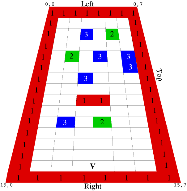 Visualisation of the map. Ah, now we're getting somewhere. We start at the viewer position (marked V), and cast out rays sweeping across the screen. For each ray cast, we will be stepping through the map (away from the viewer position) until we reach a square that contains something.
Why two rays, then?The reason we use two rays is because it is time consuming and pointless to step away from the viewer position in little hops, and if we used big hops there is the risk of missing corners.Instead, we can work out four constants. The first two are the distances between the viewer position and the next vertical boundary, and the distance between the viewer position and the next horizontal boundary. The second two are the "deltas", the distance from one boundary to the next. Pythagorean maths.
The normal way to calculate the hypotenuse is to know that the square of the hypotenuse is the sum of the squares of the other two sizes. One side is 1, the size of a map square. The other side one plus the square of the Y ray divided by the square of the X ray, which indicates how far the X ray must travel in the Y direction in order to make an X step. I'm not entirely sure how this works, it just does so I'm not going to argue.
But how far is the X step? That's the delta. It is derived from This diagram, actually, was the breakthrough that I needed to understand how raycasting works. I knew the basic principle (it's not hard), but not how it was actually done. I'm still not entirely sure how the SRQ calculation works, but seeing how it was used to derive the hypotenuse and thus the step value, it makes a lot more sense now.
Now that we know the size of the triangle (and thus our delta), we can simply fudge this with our current offset within a map square to determine a location representing how far the ray has to travel for each step of a square. In this case, as it's the X ray, it has to go up 1.85 squares in order to go left one square. It doesn't have to precisely hit the edge of the correct square, it just has to be within the square and in correct ratio with the Y ray in order that we can tell which one hit first should they both result in a hit.
You'll notice I'm talking about X rays and Y rays. This is correct. You see, if we sent out just one ray, we would be endlessly calculating the size of the next step from our current ray position. This would be a lot of, mostly unnecessary, work.
We keep track of the horizontal boundaries and the vertical boundaries separately. After we check a ray, the next step point is added to it. This works because our rays always move in a straight line, together. So adding the appropriate delta to either the corresponding ray will simply step to the next boundary that needs to be checked.
Field of viewIn order to create a good looking result, we need to sweep from left to right, but with restraint. With a squarish screen, as VGA would offer, a good value is to have somewhere between 65-70° visible. This is our field of view.Human eyes have a pretty impressive field of view. If you hold out a finger in front of you, then move your arm backwards without moving your eyes, you'll still be able to see your finger when your arm is almost held out to the side. Each eye offers around 135° of vision, and the two together gets closer to around 165°.
But we are looking at a screen. A little rectangle into a virtual world. Because of this, our field of view is reduced. For a VGA/SVGA screen, a field of view of 66° is good. 
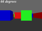
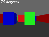
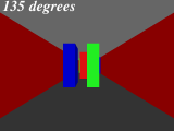
As you can see, 66° is the only one where the green square directly in front of us looks square.
Why this is important is because it determines how we sweep across the screen. In which direction does the leftmost ray go? The rightmost one? And how much is there between each screen column? 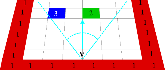 The leftmost and rightmost rays.
Render speedJust by way of example, on a Pi 3B+ (1400 MHz), drawing the screen 100× in MODE 28 results in the following speeds.These should be taken with a pinch of salt as it's only the render, there's nothing else, and it relates to this machine. Other machines (Pi 1B, Titantium, RPCEmu, etc) will obviously be different. But it's an interesting exercise in variations. Four source versions were created:
What we can see from this is that removing comments can speed up a program, but changing SWI names to numbers makes little difference in reality (it calls ColourTrans to set the colour for each strip). However, as I said above, it's this version of the code tested on this machine (which due to looping and such isn't identical to the code given here). It's not an absolute, just a comparison of one method against another.
Now for some code!This code makes much use of floating point. I trust the above chart indicates the RISC OS specific issue where we get screwed due to a continued reliance upon an emulated floating point maths processor...which is nuts when most (if not all) current ARM devices offer hardware floating point maths.Anyway, enough exposition, let's start looking at some source.
Getting startedREM >raycast1 REM REM Rick's simple ray-caster, version 1 REM https://heyrick.eu/blog/index.php?diary=20230114 REM REM Basic demonstration of principle REM REM The principle is as described by Lode Vandevenne at REM https://lodev.org/cgtutor/raycasting.html REM REM What's worth noting here is that we do *NOT* REM work in degrees like a normal ray-caster, so REM the code that follows is rather more compact REM than you may see in other places, but it does REM require competent floating point maths support. REM ON ERROR PRINT REPORT$+" at "+STR$(ERL) : END REM 640x480 in 256 colours; it's VGA so REM everything ought to support this. MODE 28 REM The physical size of the screen width% = 640 height% = 480 This sets up an error handler, picks a 256 colour VGA mode (MODE 28), and defines the screen dimensions.
REM The size of the 2D map
REM Let's keep it simple for now
mapx% = 16
mapy% = 8
DIM map%(mapx%, mapy%)
FOR loopy% = 7 TO 0 STEP -1
  FOR loopx% = 0 TO 15
    READ map%(loopx%, loopy%)
  NEXT
NEXT

REM 0 = Empty
REM 1 = Red square
REM 2 = Green square
REM 3 = Blue square
DATA 1,1,1,1,1,1,1,1,1,1,1,1,1,1,1,1
DATA 1,0,0,0,3,3,0,0,0,0,0,0,0,0,0,1
DATA 1,0,2,0,0,0,0,0,0,0,0,0,0,0,0,1
DATA 1,0,0,0,3,0,0,0,1,0,2,0,0,0,0,1
DATA 1,0,3,0,0,0,3,0,1,0,0,0,0,0,0,1
DATA 1,0,0,0,2,0,0,0,0,0,3,0,0,0,0,1
DATA 1,0,0,0,0,0,0,0,0,0,0,0,0,0,0,1
DATA 1,1,1,1,1,1,1,1,1,1,1,1,1,1,1,1
REM                             /|\
REM                              |
REM Viewer is here, fourth row up. looking to the LEFT.
Now the map is defined. As indicated, there are four square types - red, green, blue, and empty.
REM Note that as of now, it's lots of floating point maths


REM Where in the map does the viewer start?
ourx = 14
oury = 4

REM Looking to the left
xdir = -1
ydir = 0

REM The projection plane, in 2D
REM This is perpendicular to the direction.
xproj = 0
yproj = 0.65


REM yproj being 0.65 above corresponds to a field of view of
REM about 66 degrees, which is a good value for a old style
REM squarish screen, such as the VGA mode used here.
REM If using a 16:9 display, you'll need a wider field of view
REM because of the extra width. Try 0.85 which equals a field of
REM view of about 80 degrees.
REM
REM To convert the above value into degrees for a viewing angle:
REM   value = 0.65
REM   PRINT ((ATN(value / 1) * 2) / PI) * 180
REM (this converts the value into radians, and then into degrees)
REM
This sets up the initial map location (14,4), and also defines the direction and projection plane values. These are perpendicular to each other.
Here is an example of how to perform a rotation to whatever angle. PI means to rotate 180°, as radians are PI×2 for a complete circle.
REM Rotate 180 degrees
rot = PI

oldx = xdir
xdir = (xdir * COS(rot)) - (ydir * SIN(rot))
ydir = (oldx * SIN(rot)) + (ydir * COS(rot))

oldx = xproj
xproj = (xproj * COS(rot)) - (yproj * SIN(rot))
yproj = (oldx * SIN(rot)) + (yproj * COS(rot))
Note that if you get values like
BASIC only starts doing this at E-3, which means the value is
That's it for the setup. No, seriously, that's it.
There are no complicated sine/cosine tables to build.
Drawing the backgroundWe shall simply set a dark grey floor and lighter grey ceiling.
REM Draw the floor
GCOL 48, 48, 48  : REM Dark grey
RECTANGLE FILL 0, 0, (width% << 1), height%

REM And now the ceiling
GCOL 98, 98, 98 : REM Lighter grey
RECTANGLE FILL 0, height%, (width% << 1), height%
The
You could also use To give an idea of what I mean by the ECF dithering, here's an example with the colours fiddled to show the effect. Zoom in, you'll see what I mean. 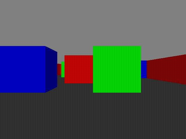 Obvious dithering is obvious.
Casting raysThis is where all the magic happens.
REM Now, cast rays for each scrcol across the screen, starting from the left.

FOR scrcol% = 0 TO (width% - 1)

  REM Let's do the easy inits first.

  REM For now, let's look to see what map location we are in.
  mapx% = ourx
  mapy% = oury
  REM We use an integer here in order to lose the fractional part,
  REM as in this case we don't care how far along in any position
  REM the viewer is, only which block matches where the viewer is.

  REM These two values represent the distance from our current
  REM (exact) location to the next square boundary. This is
  REM updated as we step along.
  xedge = 0
  yedge = 0

  REM The step values are -1 if it's a negative step, or 1 if it's a
  REM positive step. Initially zero as the stepping hasn't been set up.
  xstep% = 0
  ystep% = 0

  REM Has a wall been hit?
  wallhit% = FALSE

  REM Which side was hit? FALSE for an X side, TRUE for a Y side
  side% = 0

  REM This will be the distance to the actual wall that we're going
  REM to draw on the screen.
  towall = 0
As the comment says, we do the simple stuff first. Now for the not-so-simple stuff. ☺
  REM Now for the freaky maths

  REM Calculate our angle offset for the desired screen column.
  REM This goes from -1 on the left, to 0 in the middle, to 1 on the right.
  angle = (2.0 * (scrcol% / width%)) - 1

  REM Now set up two rays. Remember when we are talking about X and Y
  REM we are talking about the GRID that represents the array that our
  REM map is in. It isn't X,Y on the screen, or in some 3D space, it
  REM is the imaginary X,Y divisions between array elements.
  REM Or, to put it more simply, imagine that you have written the
  REM contents map% on a piece of squared paper like you used in maths
  REM class. The horizontal lines are your X positions, and the vertical
  REM lines are your Y positions.
  xray = xdir + (xproj * angle)
  yray = ydir + (yproj * angle)

  REM Now we work out how far we must step from one square edge to
  REM the next. Since the rays travel in a straight line, we only
  REM need to calculate this once.
  IF (xray <> 0) THEN xdelta = ABS(1 / xray) ELSE xdelta = 12345678
  IF (yray <> 0) THEN ydelta = ABS(1 / yray) ELSE ydelta = 12345678

  REM To explain the above a little better, the actual calculation
  REM would be:
  REM   xdelta = SQR(1 + (yray * yray) / (xray * xray))
  REM but because we already did some of this calculation when sorting
  REM out xray/Y above, and we're only interested in the RATIO
  REM between the X and the Y, all of this can be simplified down to
  REM simply dividing 1 by the ray distance.
angle performs a sweep across the screen with -1 being the left, 0 being the centre, and 1 being the right.
The only thing that needs explaning here is why we're setting the delta to be 12,345,678. It's a dummy value that is far too large to be encountered normally, but non-zero so there's no risk of causing an FP exception (like divide by zero). It's basically setting that ray so far away that we'll be stepping the other one repeatedly until something is hit.
Now we perform the appropriate calculation for each ray depending upon whether it's positive (up/right) or negative (down/left).
  REM Now we work out which stepping to use, and our initial distance
  REM to the edge of the current square.
  IF ( xray < 0 ) THEN
    REM We're moving leftwards in the map
    xstep% = -1
    xdist = ( ourx - mapx% ) * xdelta
  ELSE
    REM We're moving rightwards in the map
    xstep% = 1
    xdist = ( (mapx% + 1) - ourx ) * xdelta
  ENDIF

  IF ( yray < 0 ) THEN
    REM We're moving downwards in the map
    ystep% = -1
    ydist = ( oury - mapy% ) * ydelta
  ELSE
    REM We're moving upwards in the map
    ystep% = 1
    ydist = ( (mapy% + 1) - oury ) * ydelta
  ENDIF
We now know our step values and directions (a map square at a time) as well as our initial starting point (the first boundary), to which the delta (distance to the next boundary) is added.
Now it's time to actually cast the ray.
  REM Now look for a wall
  WHILE ( wallhit% = FALSE )
    IF ( xdist < ydist ) THEN
      REM The next X boundary is closer, so let's step to it
      mapx% += xstep%
      xdist += xdelta
      side% = FALSE
    ELSE
      REM The next Y boundary is closer, so let's step to it
      mapy% += ystep%
      ydist += ydelta
      side% = TRUE
    ENDIF

    REM Was something hit?
    IF ( map%(mapx%, mapy%) <> 0 ) THEN wallhit% = TRUE
  ENDWHILE

  REM Do you see how the two rays worked here? They are both
  REM being cast together at the same time, and we're simply
  REM stepping to look at whichever happens to be the closest.
Yup. That's it. If nothing has been hit (the map square is a zero), then we simply increment whichever ray is the shortest one, and check again. If we're going at, say, a 45 degree angle then the two rays will leapfrog each other until something is hit. If it's a steeper angle, then one ray may be bumped a lot while the other doesn't move as often. You can visualise this yourself with a piece of squared paper. Since the closest ray is the one that hit, we can also use this to tell which side (top/bottom or left/right) was hit. This allows us to add some subtle shading to make things stand out better.
Now we need to correct the ray's 'hit' location to determine the actual wall distance. REM Now that we know that something has been hit, we can work
REM out the wall distance. This is easy, we simply subtract the
REM delta that we stepped over from the accumulated distance to
REM the next side.
IF side% = FALSE THEN
REM It's an X boundary
towall = xdist - xdelta
ELSE
REM It's a Y boundary
towall = ydist - ydelta
ENDIF
IF (towall = 0) THEN towall = 1
The offset at the end is so we don't have a projection 'through' the wall if we're close to it. That would be bad. Kittens would suffer.
So now we know our three important things. We know what sort of wall was hit (from the map), we know what side was hit, and we know how far away it is (thus how big to size it).
  REM Now we have the wall distance, work out how big this line should be
  drawsize% = height% / towall

  REM Now work out the lowest and highest pixel to actually draw on
  REM the screen; clipping it if it goes off the screen.
  drawbot% = (-drawsize% / 2) + (height% / 2)
  IF ( drawbot% < 0 ) THEN drawbot% = 0

  drawtop%   = ( drawsize% / 2) + (height% / 2)
  IF ( drawtop% >= height% ) THEN drawtop% = ( height% - 1)
The horizontal centre of the screen is the point where the floor and ceiling meet. The walls are centred on this point, growing in size (both up and down) as they are closer. This creates the illusion of distance. There's only one more thing that we need, and that's to work out the appropriate colours.
  REM Now work out what colours we want
  col% = 127
  IF (side% = FALSE) THEN col% += 128
  CASE map%(mapx%, mapy%) OF
    WHEN 1 : GCOL col%, 0, 0 : REM Red
    WHEN 2 : GCOL 0, col%, 0 : REM Green
    WHEN 3 : GCOL 0, 0, col% : REM Blue
  ENDCASE
Horizontal boundaries are drawn in half-brightness colour, and if it's a vertical boundary, it's full brightness. It's visually unrealistic, but helps the illusion of three dimensions by making the different sides stand out. Verticals are full brightness because we begin facing left, so it's what we'll see head on.
Finally, plot this sliver of wall to the screen, and loop around for the next one.
  REM And, finally, draw the line, with correction between
  REM OS units and pixels for MODE 28.
  MOVE (scrcol% << 1), (drawbot% << 1)
  DRAW (scrcol% << 1), (drawtop% << 1)

NEXT

IF NOT(INKEY(-3)) THEN
  OSCLI("ScreenSave $._3dscene"+MID$(TIME$,17,2)+MID$(TIME$,20,2)+MID$(TIME$,23,2))
ENDIF
The ScreenSave at the end drops a copy of the rendered scene to your storage, as "_3dsceneHHMMSS" in the root directory of the current filing system, where HHMMSS is the current time, unless you hold down the Alt key.
Let's try that without the commentaryHere's the whole program again, without comments and without being split up. The whole program this time.
REM >raycast1
REM Rick's simple ray-caster, version 1
REM Basic demonstration of principle

ON ERROR PRINT REPORT$+" at "+STR$(ERL) : END

MODE 28
width% = 640
height% = 480

mapx% = 16
mapy% = 8
DIM map%(mapx%, mapy%)
FOR loopy% = 7 TO 0 STEP -1
  FOR loopx% = 0 TO 15
    READ map%(loopx%, loopy%)
  NEXT
NEXT

REM 0 = Empty; 1 = Red; 2 = Green; 3 = Blue
DATA 1,1,1,1,1,1,1,1,1,1,1,1,1,1,1,1
DATA 1,0,0,0,3,3,0,0,0,0,0,0,0,0,0,1
DATA 1,0,2,0,0,0,0,0,0,0,0,0,0,0,0,1
DATA 1,0,0,0,3,0,0,0,1,0,2,0,0,0,0,1
DATA 1,0,3,0,0,0,3,0,1,0,0,0,0,0,0,1
DATA 1,0,0,0,2,0,0,0,0,0,3,0,0,0,0,1
DATA 1,0,0,0,0,0,0,0,0,0,0,0,0,0,0,1
DATA 1,1,1,1,1,1,1,1,1,1,1,1,1,1,1,1

ourx = 14
oury = 4
xdir = -1
ydir = 0
xproj = 0
yproj = 0.65

GCOL 48, 48, 48
RECTANGLE FILL 0, 0, (width% << 1), height%
GCOL 98, 98, 98
RECTANGLE FILL 0, height%, (width% << 1), height%


FOR scrcol% = 0 TO (width% - 1)
  mapx% = ourx
  mapy% = oury
  xedge = 0
  yedge = 0
  xstep% = 0
  ystep% = 0
  wallhit% = FALSE
  side% = 0
  towall = 0

  angle = (2.0 * (scrcol% / width%)) - 1
  xray = xdir + (xproj * angle)
  yray = ydir + (yproj * angle)
  IF (xray <> 0) THEN xdelta = ABS(1 / xray) ELSE xdelta = 12345678
  IF (yray <> 0) THEN ydelta = ABS(1 / yray) ELSE ydelta = 12345678


  IF ( xray < 0 ) THEN
    xstep% = -1
    xdist = ( ourx - mapx% ) * xdelta
  ELSE
    xstep% = 1
    xdist = ( (mapx% + 1) - ourx ) * xdelta
  ENDIF

  IF ( yray < 0 ) THEN
    ystep% = -1
    ydist = ( oury - mapy% ) * ydelta
  ELSE
    ystep% = 1
    ydist = ( (mapy% + 1) - oury ) * ydelta
  ENDIF

  WHILE ( wallhit% = FALSE )
    IF ( xdist < ydist ) THEN
      mapx% += xstep%
      xdist += xdelta
      side% = FALSE
    ELSE
      mapy% += ystep%
      ydist += ydelta
      side% = TRUE
    ENDIF

    IF ( map%(mapx%, mapy%) <> 0 ) THEN wallhit% = TRUE
  ENDWHILE

  IF side% = FALSE THEN
    towall = xdist - xdelta
  ELSE
    towall = ydist - ydelta
  ENDIF
  IF (towall = 0) THEN towall = 1


  drawsize% = height% / towall
  drawbot% = (-drawsize% / 2) + (height% / 2)
  IF ( drawbot% < 0 ) THEN drawbot% = 0
  drawtop%   = ( drawsize% / 2) + (height% / 2)
  IF ( drawtop% >= height% ) THEN drawtop% = ( height% - 1)

  col% = 127
  IF (side% = FALSE) THEN col% += 128
  CASE map%(mapx%, mapy%) OF
    WHEN 1 : GCOL col%, 0, 0
    WHEN 2 : GCOL 0, col%, 0
    WHEN 3 : GCOL 0, 0, col%
  ENDCASE

  MOVE (scrcol% << 1), (drawbot% << 1)
  DRAW (scrcol% << 1), (drawtop% << 1)

NEXT

IF NOT(INKEY(-3)) THEN
  OSCLI("ScreenSave $._3dscene"+MID$(TIME$,17,2)+MID$(TIME$,20,2)+MID$(TIME$,23,2))
ENDIF

END
And...?There's loads more to cover. Wall textures, for example. Not to mention... movement!
Writing this has taken a long time. Weeks of reading through all sorts of sources, performing endless calculations with my calculator (and getting most wrong until pennies were dropped). Then the diagrams and graphics and such.
However I very much hope I've done a reasonable job of showing how raycasting works. There are other methods, but the underlying principle is the same. You translate a direction into a pair of distances representing the next X boundary and the next Y boundary, then you step the smallest each time until something is hit. A bit of maths can turn the value into an absolute distance which directly determines how big to draw the wall piece.There, a one-sentence summary. Now, all you're missing is the source (Zip, 4173 bytes). Have fun!
Your comments:Please note that while I check this page every so often, I am not able to control what users write; therefore I disclaim all liability for unpleasant and/or infringing and/or defamatory material. Undesired content will be removed as soon as it is noticed. By leaving a comment, you agree not to post material that is illegal or in bad taste, and you should be aware that the time and your IP address are both recorded, should it be necessary to find out who you are. Oh, and don't bother trying to inline HTML. I'm not that stupid! ☺
|   
(Felicity? Marte? Find out!)
📺 The SIBA stories 📹
It's a simple substring match.
Last read at 21:19 on 2025/04/02.


| |||||||||||||||||||||||||||||||||||||||||||||||||||||||||||||||||||||||||||||||||||||||||||
| Next entry - 2023/01/20 Return to top of page |
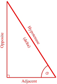 What we actually do here is to solve the triangle first. We know one side of the triangle will be '1', as it traverses one square. The angle is simply the current angle we're actually facing. For example, X = -0.54. It is a negative value because it's to the left. Left and down are negative, up and right are positive.
| © 2023 Rick Murray |
| Retrieved from https://heyrick.eu/blog/index.php?diary=20230114 on 2nd April 2025 |