|
The positions of the bump
sensors
 RickBot contains twelve
individual sensors. RickBot contains twelve
individual sensors.
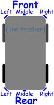
These are mounted centre front,
centre rear, and at each corner. This is shown in the
picture to the right. The sensors are referred to as
"bump" sensors as they are designed to be triggered
whenever RickBot is about to run into
something.
Data
input
There are five inputs
used:
|
PA0
|
|
Left |
|
PA1 |
|
Right |
|
PA2 |
|
Front |
|
PA3 |
|
Rear |
|
CA1 |
|
Bump
flag |
The actual position of the
bump is multiplexed onto the four location bits; hence
"front left" will set "front" and "left". At the same
time, the "flag" will be set. This connects to
CA1 and will cause
an interrupt to be generated.
This system could
"fail" if, for example, we hit something hard enough
that momentum carries us even when we switch off the
drive system. In this case, it is possible for multiple
sensors to be set; such as "front left" and "front". As
the sensors are multiplexed, all relevant
inputs will be activated, so RickBot will 'see'
front and left, and think it is a
front-left sensor hit. While this is not strictly
desirable, the response will be to move in reverse (and
left) which will take us away from the
obstacle.
The interrupt handling
must give a high priority to the bump
sensors. Upon a sense, the motors must be instantly
stopped (possibly also 'locked' in their current
position if this is possible with the motors utilised).
Only once this has been done should we even attempt
to work out what corrective action to
take.
Corrective
action
The course of
corrective action depends upon the purpose and desired
complexity of the firmware. The most obvious solution is
to move the other way. More complex solutions involve
logic akin to "move backwards and left (or
right) for two seconds, then continue". This could
give us a limited ability to work around
obstacles. Perhaps the most complex part of the firmware
would be how to handle a bump when handling a bump - if
our moving back causes us to fit
something.
Doubling
up
You may have noticed that this
description only describes six sensors. This is because
each sensor is doubled, as shown below:

There is a sensor mounted on
the 'body' to detect if we're about to hit something,
and there is another sensor mounted underneath to detect
running out of floor. Each triggers the same signals -
there is no difference between "object" and "no floor"
because the resulting behaviour is the same, and it will
be until I've perfected the "ion drive" which would
allow RickBot to fly...
Potential
problems with the ground
sensor
At this early stage in planning, the
ground sensor is a switch which 'rubs' the floor. Upon
running out of floor, the switch sensor will drop enough
that the switch opens. You will, obviously, have noticed
that the switches work in opposition - the object
sensors 'close' to signal, while the floor sensors
'open'. A logic gate is used to invert the floor signals
accordingly.
To be brutally honest, I can
see numerous flaws in this design. The switches will
have to work correctly in both directions, and at all
speeds, not to mention turning. Furthermore, the sensors
must be accurate so they do not supply false
signals. I'll have to wait until RickBot is active to assess
this method of sensing.
Bump sensor
logic
Below is a diagram of
the logic used to implement the bump sensors and
activate the correct signal at the correct times. It is,
basically, a number of OR gates. Please note that the
lowest gate would probably be constructed out of spare
gates, instead of increasing the IC count just for a
4-input gate. It has been done like this in order to
make the diagram clearer.
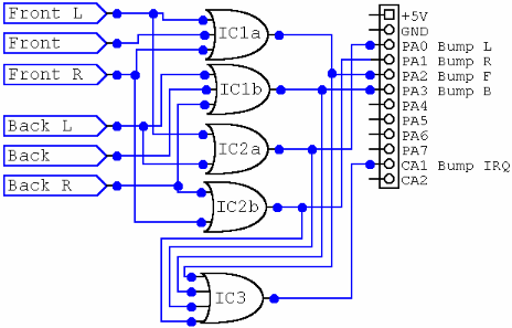
Please note that this diagram makes
no mention of interface pins not directly related to the
bump sensing. The complete schematic for the sensor
interface board may be found in Sensor
Circuitry
.
|