|
Possibilities
This section describes things
that could be added to RickBot's
sensing. Find out more; as well as
information on the options selectors - which
doesn't really have a section of its own to fit
into.
The options
switches
It may be desired that slight
modifications be made to the operation of the application
code. Now there are two ways you can do this.
The hard way is to hardwire the modifications,
make a set of firmware files, and program a set of
EPROMs. When you want a different behaviour, pick the
EPROM with the required options and plug it in.
The
easy way, however, is to plug
a SIL switch, or a set of jumpered links, into the
expansion port. This contains eight switches that can be on
or off, memory-mapped. The application code reads this, and
sets its behaviour according to those switches.
Here is a schematic for this:
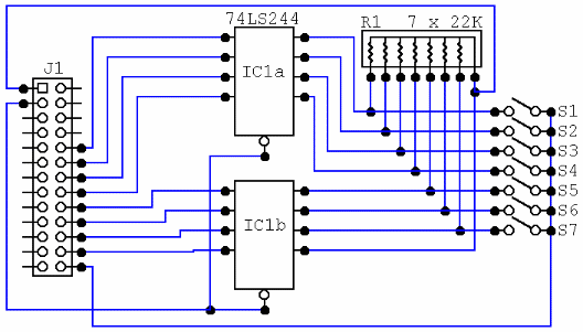
The
eighth input is connected directly to +5V in order that the
application code detect the options board is present. It
is wired to UNUSEL (at
&A200). An easy
method of detection is to check &A200, &A210, and &A220. What is read back
from all three locations will be identical if the board
is connected - because the address lines are not
connected to anything so the response will be the
same.
The following
options are defined:
|
Switch |
OFF action |
ON action |
|
SW1 |
Line tracking
disabled. |
Line tracking
enabled. |
|
SW2 |
Track
black line on white
. |
Track
white line on black (inverted)
. |
|
SW3 |
currently
unassigned |
currently
unassigned |
|
SW4 |
currently
unassigned |
currently
unassigned |
|
SW5 |
currently
unassigned |
currently
unassigned |
|
SW6 |
currently
unassigned |
currently
unassigned |
|
SW7 |
currently
unassigned |
currently
unassigned |
At this stage, the behaviour
when no options board is connected is
undefined. It is likely that the application code will
simply behave as if all switches were in their
off position.
Marking the end of the guide
track...
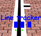 An additional extension is the
implementation of a third sensor, offset to the
left (or right) of the others. This could be used
to sense an end of trackmarker, perhaps as shown in the diagram to the
right. An additional extension is the
implementation of a third sensor, offset to the
left (or right) of the others. This could be used
to sense an end of trackmarker, perhaps as shown in the diagram to the
right.
In this case, the third sensor
will be connected via a logic gate to switch on
both the left and right sensor signals (PA4 and PA5
).
As you can see, the end-of-guide
marker is a sideways version of the guide track. This is
to provide a strong ON-OFF-ON signal to the application
code; because the third sensor - looking down over the
ground - may receive numerous false readings. By knowing
the motor speed, it should be possible to set up a
response based on time (which, in turn, is based on
speed). Thus, it could be ON ~30ms, OFF ~30ms, ON
~30ms. |