The
schematic
Because of the differences in
loading, voltage, and general requirements, the
sensor circuitry is provided on a separate board to that
of the motor controller. It works completely off
the +5V supply from Amélie (the main board),
and basically is a few logic gates connected to
switches. It provides all of the necessary connections
for the bump sensors and the line
tracker.
Here is the
complete schematic of the interface board:
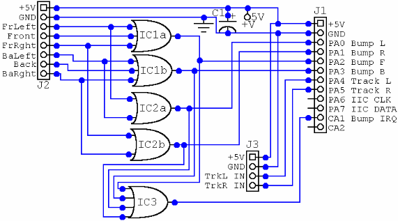
While I²C and CA2 are provided by the
interface cable, they are not required and are thus
unconnected.
C1 is an electroyltic capacitor. The exact
value is not terrible relevant so long as it is
sufficient to adequately smooth the power rails. I'd go
for around 2000µF, but then I've always preferred meaty
capacitors. In actuality, 100µF will probably be
sufficient!
IC1 is a 4075 Triple 3-input OR
gate.
IC2 is a
4071 Quad 2-input OR
gate.
IC3 is a
4072 Dual 4-input OR gate.
It might seem
wasteful to use three ICs. There is an unused 3-input OR
gate and and two unused 2-input OR gates. These
could be used to implement the functions
required of the 4072; and in that there is an
unused 4-input OR gate. You'd be right. It is
wasteful. But not without reason. I've been programming
and building things long enough to know that the future
is not predefined. I have several OR gates kicking
around on my sensor board, not to mention a connection
to an interrupt-causing pin (CA2) that is currently unused.
Perhaps, some way down in the future, I could add more
features by piggybacking some wire links directly to the
unused pins? What, then, is more wasteful? Spending an
unnecessary £1 today for a logic gate, or
having to design an entirely new board for a small
addition. You may curse me forever for this
implementation, or in a year's time when you want to try
something new you may think "hot damn! there's a 4-input
OR gate here! just what I needed! awesome!". :-)
Security
There is no need for
buffering as we are providing inputs to the system
VIA.
There is no need for voltage regulation
as we run from the primary +5V supply. If this goes
haywire, more will suffer than the interface
board!
We take very little power, and there is a
smoothing capacitor so the switching has no side
effects with the main board.
No particular isolation
is necessary (asides from "common sense") as we are only
providing "on/off" signals for sensing, and not
a clocked high-frequency data bus (or the
like).
Example
layout
The actual layout
used in the first version of RickBot is going
to be built on veroboard. However just as an exercise
(and because it is so easy!), I've put together an
autorouted circuit just to see how compact it
would be. This is shown at 200% zoom - but then
I expect you know roughly how big 14-pin logic ICs
are...
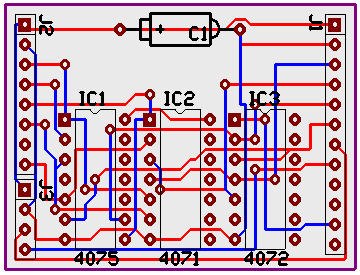
It's a two layer board. Blue is
one layer, red t'other.
The board
layout
Sorry! This is not
currently
available...