It is the 1727th of March 2020 (aka the 21st of November 2024)
You are 3.145.103.169,
pleased to meet you!
mailto:blog-at-heyrick-dot-eu
...the end of the first week of the year at work. Funny how this week lasted so much longer than my week of holiday...
Mod my 'scope
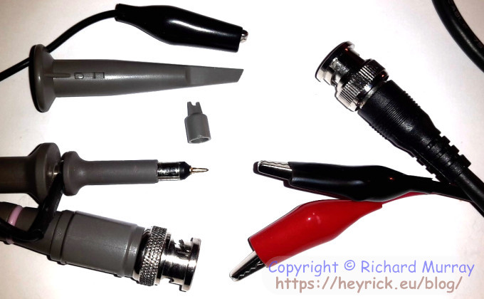
On the right, the basic croc-clip style test probes supplied with the DSO138. On the left, a proper 1:10 oscilloscope probe along with various attachments. Now the benefit of a real probe is that it is pointy so can be used with rather more finesse than a croc clip. In addition to this, the grey funnel thing hides a spring loaded hook so the probe can be attached to a wire with minimal risk of interfering with other parts of the circuit. The small grey lug is a 'shoe' that can go over the probe end to permit it to touch specific legs of an integrated circuit without worrying about slipping and shorting adjacent legs. It makes sense to use a proper probe.
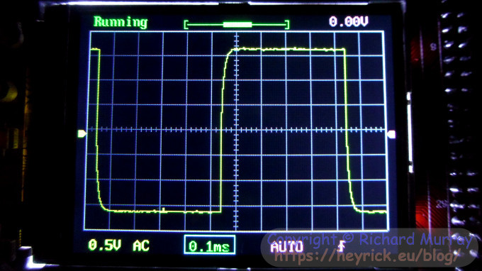
The oscilloscope is calibrated to match the frequency response of the croc clip probes. Calibration is performed by altering a capacitor trimmer to adjust the capacitance that appears between the input probe and the ground probe. Incorrect calibration means higher frequency signals will either have rounded edges, or 'bounce' afterwards.
Here's an example of too little, note the rounded edges:
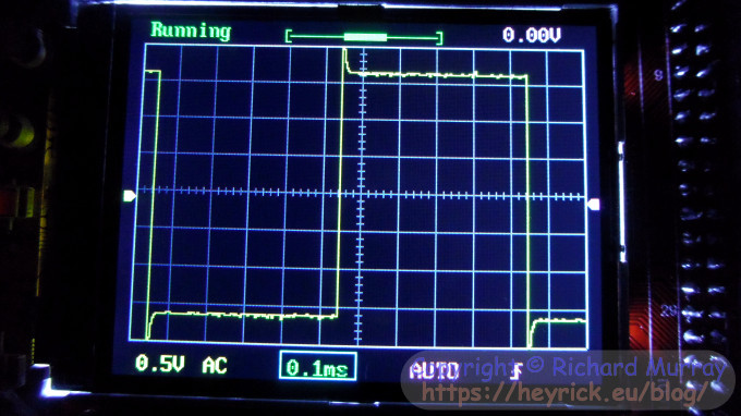
Here's an example of too much, and it's obvious what's wrong with this:
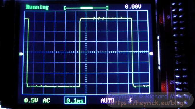
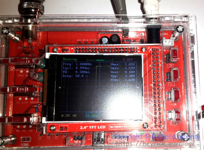
This is what the signal is supposed to look like:
Now, if I had a bare circuit kicking around, there would be no problem with capacitance. Getting to the trimmers is easy, but the device is utterly unprotected so really it needs to be in a case. Somebody that spends an afternoon building something moderately complex and doesn't put it in a box afterwards is asking for a world of disappointment.
But if it's in a box, how does one get to the trimmers?
One doesn't.
Unless one happens to have a small rounded grinder ball on a stick (actually designed for engaving glass!) and a smallish power drill. Then one can make a god-awful mess with little bits of plastic (detritus from the drilling) all over the place. Such a mess I had to strip the case right down to clean it all out. On the up side, I worked out where that other bit was supposed to go, so I've built it correctly now. ☺
If you look carefully, you'll see two small holes to the left of the LCD.
Yes, the LCD is slightly off centre (this is a fake, not a real JYE kit!). It looks horrible in this photo, but in real life it isn't so obvious. Besides, one is supposed to
be looking at the information on the display, not the display itself!
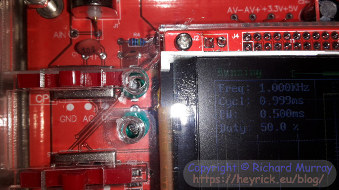
Here's a closer-upper:
It's a shame that I didn't get them lined up nicely, but it was done freehand using a power drill, so it's not so bad. It achieves the aim of a hole into which a small screwdriver may be inserted to allow the trimmer to be twiddled.
The upper trimmer (C6) is for the 1V range, and the lower trimmer (C4) is for the 0.1V range. There's no adjustment for the 10mV range.
Your comments:
Please note that while I check this page every so often, I am not able to control what users write; therefore I disclaim all liability for unpleasant and/or infringing and/or defamatory material. Undesired content will be removed as soon as it is noticed. By leaving a comment, you agree not to post material that is illegal or in bad taste, and you should be aware that the time and your IP address are both recorded, should it be necessary to find out who you are. Oh, and don't bother trying to inline HTML. I'm not that stupid! ☺ ADDING COMMENTS DOES NOT WORK IF READING TRANSLATED VERSIONS.
You can now follow comment additions with the comment RSS feed. This is distinct from the b.log RSS feed, so you can subscribe to one or both as you wish.
David Pilling, 6th January 2017, 23:04
On my probes the thing to twiddle is part of the plug that goes into the oscope. I've never probed stuff - depends on the work you're doing, someone fixing a radio would probably probe around. I always want permanent connections - leads terminating in "Du Pont" plugs (as used with breadboards) would be good. Mini-grippers (hooks as they sometimes come out on ebay) could be good - more in keeping with modern small components than croc clips. It would be nice to replace the trimmers with reverse biased diodes (the ones with lots of capacitance - varicap diodes) and have the software sort out the trimming.
Wonder if there is any customisation of this scope going on - I'd be thinking how to do screen shots and how to get data out of it.
This web page is licenced for your personal, private, non-commercial use only. No automated processing by advertising systems is permitted.
RIPA notice: No consent is given for interception of page transmission.