It is the 1727th of March 2020 (aka the 21st of November 2024)
You are 3.138.101.219,
pleased to meet you!
mailto:blog-at-heyrick-dot-eu
JYE Tech DSO Shell
Well... That was quick.
Today, a small parcel arrived. Apparently from Holland, so maybe this was dispatched from the European warehouse instead of the Chinese one?
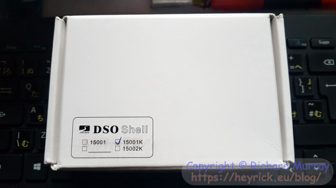
The packet was one of those crappy plastic bags that you wonder how it would survive the postal service. However the content, this box, was wrapped in several layers of plastic sponge to protect it.
The kit is smaller than I was expecting, but then when you think about it a fair bit of savings can be made by having electronic switches instead of manual, discarding the USB and two serial ports (actually, one of the serial ports remains inside), and rearranging things to make better use of the available space. The original DSO design, that I built the clone kit of, was "compact". This is just dinky and cute.
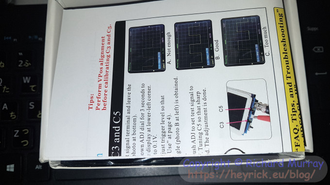
Opening up the box, that was security sealed - a nice touch - made me smile. There within the box were the instructions. In colour. Not a naff photocopy.
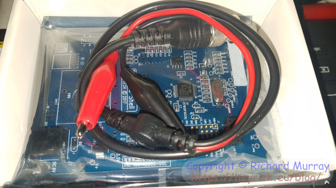
Underneath the instructions, the probe. Still two croc clips leading to a BNC socket. I wonder why they supply that instead of a traditional pointy-probe? Underneath it, a proper JYE DSO Shell, complete with serial number sticker.
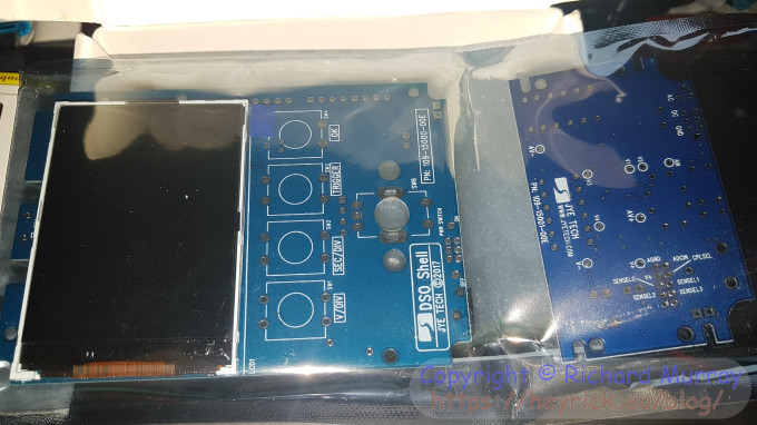
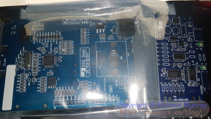
On the left, the main board with the screen pre-attached. On the right, the interface board. In both cases, the exciting stuff is on the other side.
Which is this side. It's still the STM32F103C8 microcontroller, which I shall recap as a ~72MHz ARM Cortex-M3 (from an 8MHz clock source), 64K Flash, 20K SRAM, and 12 bit 1µS ADC. However what's new here is the amount of access to other signals. Along the lower right of the board as you see it, various data and interface signals, with the UART rightmost. Also if you go about two thirds of the way to the top left from the centre of the main board, there is another collection of signals. This could be interesting for those willing to experiment. Not me, I hasten to add, but it's an interesting design choice that may make some people smile.
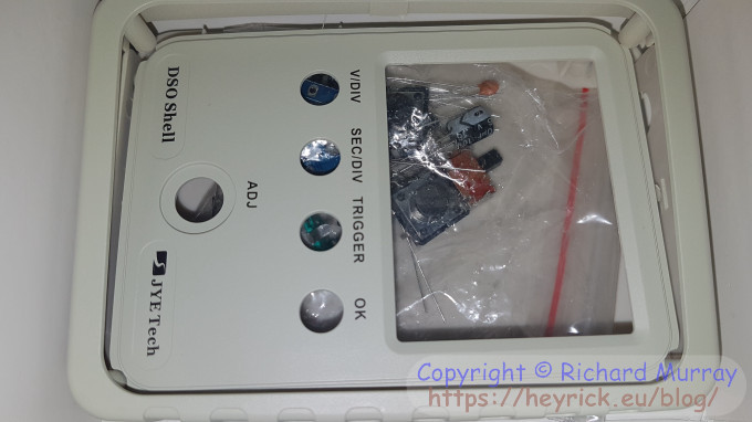
The final thing in the box is the plastic casing. While the beige is a bit boring, it is nicely printed and a matt finish, with a design that aids gripping it securely. It would be feasible, if a bit weird, to operate it single-handed using a thumb to reach over and prod the buttons. Indeed, the only real shame as I mentioned a few days ago, is that it is still tethered to planet earth by way of a socket looking for 9V DC. It surely wouldn't have been too arduous to have made the casing a little bit bigger to accommodate a PP3 (9V) battery?
Inside the casing? A bag of bits. This will be the fun part, metering all those resistors.
It is much easier this time. A spade terminal, an internal power connector (optional, but I'll fit it in case one day I want it), two slide switches, four push switches, one rotary switch, two pin headers (1×4 and 2×5), a BNC connector, sixteen resistors, four ceramic caps, and three electrolytics. I'm not going to say "easy!", but compared to assembling the DSO 138, it kind of looks like it will be.
Of course, I'll need to give it exactly the same attention to detail as I gave the DSO 138, because I'm proud that I built it and got it going first time without problems. I expect exactly the same this time around, but it doesn't take luck, it takes work. Everything gets metered and noted. Then metered again. And once more before committing to solder the part in place.
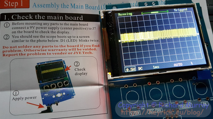
Of course, I could perform step one right away. Fire up the device, ensure it boots, and verify that "noise" is shown on the screen. I noted another little touch - when the device boots, your serial number flashes up on the screen as part of the build number.
I'll look forward to a rainy Sunday (maybe this Sunday) when I can put aside some time to do this proper justice, build it right.
Your comments:
Please note that while I check this page every so often, I am not able to control what users write; therefore I disclaim all liability for unpleasant and/or infringing and/or defamatory material. Undesired content will be removed as soon as it is noticed. By leaving a comment, you agree not to post material that is illegal or in bad taste, and you should be aware that the time and your IP address are both recorded, should it be necessary to find out who you are. Oh, and don't bother trying to inline HTML. I'm not that stupid! ☺ ADDING COMMENTS DOES NOT WORK IF READING TRANSLATED VERSIONS.
You can now follow comment additions with the comment RSS feed. This is distinct from the b.log RSS feed, so you can subscribe to one or both as you wish.
Zerosquare, 13th September 2017, 06:24
"I wonder why they supply that instead of a traditional pointy-probe?"
Cost, most probably. Proper probes are not just a piece of wire with a pointy end ; they're designed to minimize signal distortion, especially at high frequencies, so they're not that cheap. It wouldn't make sense on such a low-end scope, which is only suitable fir tinkering anyways.
This web page is licenced for your personal, private, non-commercial use only. No automated processing by advertising systems is permitted.
RIPA notice: No consent is given for interception of page transmission.