It is the 1727th of March 2020 (aka the 21st of November 2024)
You are 3.145.91.152,
pleased to meet you!
mailto:blog-at-heyrick-dot-eu
Rick's LapseCam (ESP32-Cam)
As much as I dislike the quirkiness of the C++ compiler, and the extreme lethargy of the build environment, I just can't get away from the fact that taking one of these gizmos...
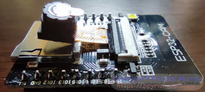
Generic clone ESP32-Cam.
...and making it do something without loads of development effort is kind of nifty.
This is one of the things where RISC OS falls down. The ESP32 has a rich set of libraries available. WiFi? Bluetooth? HTTP server? OLED? LCD? Camera? RTC? EEPROM? There are a huge selection of libraries. Pretty much anything that's electrically compatible with the chip is likely to have a library for it. My little NetRadio basically took the WiFi library, the http client library, the 16×2 IIC LCD library, and the audio chip library and combined them with some of my own code to make a basic but completely functional internet radio. The only reason I'm using a commercial unit today is that buying a second set of bits to work on making a better radio would have cost me more than buying that rather cute wooden box that does everything I could have wanted. Plus, it didn't come with an IR controller but it does have an IR sensor, so a bit of fiddling later to get my phone to act as an IR controller, and being based upon the ESP32, it has an interesting serial port.
So, now, to the ESP32 with built in camera, and it also has a built-in µSD card slot.
The camera is a bit crap. The OV2460 was released in 2005 and discontinued in 2009, but there are billions of these things. It's a fairly basic two megapixel camera as used in cheap digital cameras of its era which means lousy low-light response, somewhat indistinct details (probably rather basic Bayer filtring), washed out colours, and...
...come on, what the hell d'you want for under two euros?
Seriously, while Amazon might ship ESP32-Cam modules for around €12, you can find them on eBay and Alibaba for around €4,60 each including the camera.
This makes it an attractive price for "fiddling". Frobbing, even.
A word of warning before we begin.
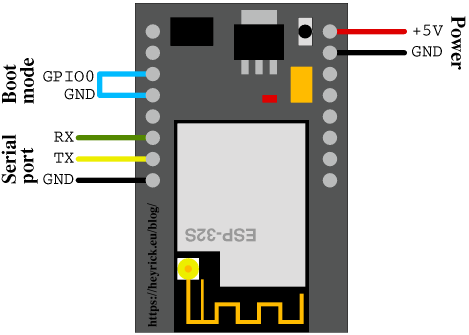
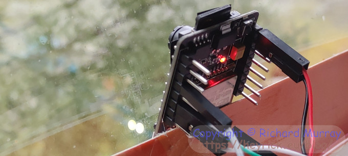
This is how I usually wire up my ESP32-Cam devices. The power is from a dedicated USB port, and not passing through the serial adaptor, as these often don't have a particularly large capacity to power the device. It's often enough for flashing the firmware, but when in use and the WiFi kicks in, the thing can often reboot as the brownout detection is triggered (that means the power dropped low enough to risk malfunctions).
The normal way to wire up an ESP32-Cam for programming.
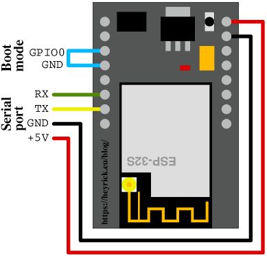
Unfortunately, many of the cheap devices are built with the GND pin next to the serial pins not connected. Which means that the device will appear completely non-responsive.
In addition, while the flashlight LED will glow dimly whilst you hold the reset button on the better modules, this doesn't happen on the cheaper ones.
So you'd be forgiven for thinking that the thing is toast. Dead. History.
It isn't. You just have to wire it up like this.
How to wire up a cheap clone ESP32-Cam for programming.
That is to say, you can't use a separate 5V power supply, as you need a common ground for serial, programming, and power and there are only two functional GND pins on the cheaper boards (even though the one bottom left is indeed marked GND and is connected to ground in the schematic).
Anyway, wire it up like that and suddenly on the serial monitor (115,200bps, 8N1) you'll see loads of crap when you hit reset if you don't have GPIO0 grounded, or the reassuring boot loader waiting for firmware upload if you do have GPIO0 grounded.
So... the project I set myself... to create a simple little time-lapse camera that takes a picture every minute and writes it to SD card. In order that it can run cool and not consume too much power, it will spend most of the time in deep sleep state (effectively turned off) until the RTC unit wakes the thing up.
In addition to this, the pictures will be saved with sequential numbers.
There is debug output on the serial port, but there is no use of the WiFi or Bluetooth capabilities of the ESP32. This is intended for exactly as it says on the tin - a simple time lapse camera that uses little power so ought to run for a good long time from batteries.
Header and includes
// LapseCam v0.01
//
// by Rick Murray
// 31st March 2023
//
//
// The ESP32-Cam will wake up every minute, retrieve a sequential number, and then
// take a photograph with that number. Once done, it'll go to sleep until the next
// minute.
//
// If there is a file on the SD card called "reset.txt", then the counter will be
// reset, and the text file then deleted.


// Basics
#include "Arduino.h"
// The camera
#include "esp_camera.h"
// The filesystem
#include "FS.h"
#include "SD_MMC.h"
// Turn off the brownout detection (stops booting)
#include "soc/soc.h"
#include "soc/rtc_cntl_reg.h"
// Control the RTC for our wakeup
#include "driver/rtc_io.h"
// Access the internal flash
#include <EEPROM.h>
#define EEPROM_SIZE 2
Remember what I said about the rich set of libraries? Well, there's the camera, access to the SD card, a FAT capable filesystem, some internal stuff, and access to the EEPROM.
Definitions
This is where various things are defined for the camera. These cheap boards are clones of the AI Thinker camera. If you have something else (like ESP-Eye or M5Stack) you'll need to look up what particular wiring your board uses. Generally, you can copy-paste from the default CameraWebServer source (in Examples).
// These pins are defined for the cheap ESP32-CAM
// board that you can find all over the place.
// They're all clones of the AI Thinker board.

#define RESET_GPIO_NUM    -1
#define XCLK_GPIO_NUM      0
#define FLASHLIGHT_PIN     4 // doubled with SD card
#define Y2_GPIO_NUM        5
#define Y3_GPIO_NUM       18
#define Y4_GPIO_NUM       19
#define Y5_GPIO_NUM       21
#define PCLK_GPIO_NUM     22
#define HREF_GPIO_NUM     23
#define VSYNC_GPIO_NUM    25
#define SIOD_GPIO_NUM     26
#define SIOC_GPIO_NUM     27
#define PWDN_GPIO_NUM     32
#define LED_PIN           33
#define Y8_GPIO_NUM       34
#define Y9_GPIO_NUM       35
#define Y6_GPIO_NUM       36
#define Y7_GPIO_NUM       39


// LED is inverted, so make some easy defines
#define LED_ON           LOW
#define LED_OFF         HIGH
Globals
RTC_DATA_ATTR int bootcount = 0;
The only global is bootcount which is how many times we have been booted since power-up. The reason this is prefixed with RTC_DATA_ATTR is to instruct the compiler that this variable lives in the RTC's memory rather than regular program memory. By doing this, the value of the variable will persist for as long as the device is powered.
All other variables do not persist, as deep sleep shuts down the RAM. The hardware literally boots from cold each time, the only thing that keeps running is the RTC.
Note that the sequential picture counter is not held in RTC memory because it is loaded from EEPROM, so there's no point. And it is loaded from EEPROM so that the sequential numbering is preserved not only over deep sleep, but also over power-down.
Getting going
void setup()
{
   int      counter = 0;
   char     filename[32] = "";
   int64_t  ticks = esp_timer_get_time();
   uint8_t  sdtype = CARD_NONE;
   uint64_t sdsize = 0;
   uint64_t sdfree = 0;

   // First thing, kill the brownout detection
   WRITE_PERI_REG(RTC_CNTL_BROWN_OUT_REG, 0);

   // Say hello
   Serial.begin(115200);
   Serial.println();
   Serial.println("Rick's LapseCam starting.");
   bootcount++;
   Serial.printf("This is boot %d since powered up.\n", bootcount);

   // Turn on the status LED as well
   pinMode(LED_PIN, OUTPUT);
   digitalWrite(LED_PIN, LED_ON);
Firstly we define some of the variables that we use. counter is the image counter (and is also used for flashing LED loops if something goes wrong). filename is the name of the file we're going to write to media. ticks is the value of the internal high resolution timer at start to allow for a more accurate delay of when to next boot. sdtype, sdsize, and sdfree are for detecting/reporting the SD card.
In order to stop the device self-rebooting should the power be 'iffy', the very first thing to do is to nuke that brownout detection.
Following that, a short message to serial port. And for the user if there's no serial port connected, to turn on the little red LED on the underside of the board.
The red LED has specific purposes:
If it's on steady for about seven or eight seconds, that's normal.
If it blinks quickly for a couple of seconds, then there was a problem initialising the camera. The device will reboot.
If it blinks really quickly for a couple of seconds, then there was a problem starting the SD card. The device will reboot.
If it blinks really quickly without stopping, there's no SD card. The device has halted, there's nothing it can do.
If it's on steady, and keeps repeating (no minute between pictures) then there was either a problem taking a picture, or more likely a failure writing to the SD card - potentially because it's run out of space.
I decided to have it reboot rather than blink the LED forever because this is a distinctive behaviour so you can tell what the problem is by what the LED is doing. I don't imagine there will be a problem taking the picture. There's a big buffer and the camera has already started up...
The flash LED is not used. However it is connected to one of the pins used by the SD interface, so it will blink when mounting the SD card, and also when writing the picture to the SD card.
This can be disabled by setting the SD card to one bit mode (slower), but I find the blinking reassuring, you can see that something is happening, a bit like the LED on a harddisc.
Setting up the camera
Nothing usual here.
   // Set up the camera
   camera_config_t config;
   config.ledc_channel = LEDC_CHANNEL_0;
   config.ledc_timer = LEDC_TIMER_0;
   config.pin_d0 = Y2_GPIO_NUM;
   config.pin_d1 = Y3_GPIO_NUM;
   config.pin_d2 = Y4_GPIO_NUM;
   config.pin_d3 = Y5_GPIO_NUM;
   config.pin_d4 = Y6_GPIO_NUM;
   config.pin_d5 = Y7_GPIO_NUM;
   config.pin_d6 = Y8_GPIO_NUM;
   config.pin_d7 = Y9_GPIO_NUM;
   config.pin_xclk = XCLK_GPIO_NUM;
   config.pin_pclk = PCLK_GPIO_NUM;
   config.pin_vsync = VSYNC_GPIO_NUM;
   config.pin_href = HREF_GPIO_NUM;
   config.pin_sscb_sda = SIOD_GPIO_NUM;
   config.pin_sscb_scl = SIOC_GPIO_NUM;
   config.pin_pwdn = PWDN_GPIO_NUM;
   config.pin_reset = RESET_GPIO_NUM;
   config.xclk_freq_hz = 20000000;
   config.pixel_format = PIXFORMAT_JPEG;

   // I don't check if PSRAM found, I know my device has it.
Starting the camera
   // Initialise with maximum memory for images
   Serial.println("Starting camera.");
   config.frame_size = FRAMESIZE_UXGA;
   config.jpeg_quality = 2;
   config.fb_count = 2; // run continual
   esp_err_t err = esp_camera_init(&config);
   if (err != ESP_OK)
   {
      Serial.printf("ERROR: Camera start failed with error &%x.\n", err);
      for (counter = 1; counter < 20; counter++)
      {
         // Blink LED so we know it failed
         digitalWrite(LED_PIN, LED_ON);
         delay(100);
         digitalWrite(LED_PIN, LED_OFF);
         delay(100);
      }
      ESP.restart(); // then hit the big red button
      return;
   }
Notice that I am starting the camera with full (UXGA) resolution, and a quality setting of two.
The usual settings used in the CameraWebServer example (quality 10) will allocate 384,000 bytes to the image buffer, so pictures that are larger than this will be clipped and it may mess things up in other ways.
By setting the quality higher (0-5), the camera library will allocate a larger 960,000 byte buffer for images, which ought to be plenty.
Set two framebuffers (fbcount = 2) so the camera is always filling the frame buffer, otherwise the settling (see below) won't work correctly.
Note - if you are using a more recent version of the SDK, there has been a change so you will need to insert the line:
config.grabmode = CAMERA_GRAB_LATEST;
so that you'll get the most recent picture. The default is to fill the buffer with pictures and stop until a buffer is free.
I do love when things are changed in incompatible ways...
Configuration being done, try to start up the camera and wibble the LED (until reboot) if this fails.
Read the EEPROM counter value
   // Read our EEPROM
   // 16 bits, files image00000.jpg -> image65535.jpg
   EEPROM.begin(EEPROM_SIZE);
   counter = EEPROM.read(0) + ( EEPROM.read(1) << 8 );
   if ( counter == 0xFFFF )
      counter = 0; // initial state is both bytes &FF
   Serial.printf("Counter for this image is %d.\n", counter);
This reads, and reconstitutes the counter value from the EEPROM.
Additionally, since the EEPROM bytes default to &FF, we trap this and set it to zero.
Release the hold on the flash LED
   // As we held the flash LED off when powered down, it must be
   // released or else the SD card won't work.
   rtc_gpio_hold_dis(GPIO_NUM_4);
Just before entering deep sleep mode, the flash is forced off. Here the enforcement is released. If this wasn't done, the DATA1 pin of the SD card would be forced off, which, uh, would cause problems when trying to access the SD card.
Given the range of GPIO on the ESP32, I don't know why P2 (the eight pins where the +5V is) is basically the same pins as the SD card, and why the flash LED is shared with the SD card. That being said, six pins are used by the PSRAM, six by the SD card, two for the serial port, one by the notification LED, and fifteen by the camera module. There might not be (m)any left!
Start up the SD card
This consists of three parts. Firstly, starting up the SD interface (error: quick flash and restart). Afterwards, verifying there's something in the interface (error: quick flash forever), and then setting up the filing system.
I also print out the media size and free space to the serial port. Useful for debugging.
   // Get the SD card running
   Serial.println("Starting SD card.");
   if ( !SD_MMC.begin() )
   {
      Serial.println("ERROR: SD Card could not be started.");
      for (counter = 1; counter < 40; counter++)
      {
         // Blink LED faster so we know it failed
         digitalWrite(LED_PIN, LED_ON);
         delay(50);
         digitalWrite(LED_PIN, LED_OFF);
         delay(50);
      }
      ESP.restart(); // then hit the big red button
   }

   // Check there's something IN the SD slot!
   sdtype = SD_MMC.cardType();
   if (sdtype == CARD_NONE)
   {
      Serial.println("ERROR: No SD card! Halting.");
      while (true)
      {
         // Just loop, this isn't a glitch, it's a show stopper
         digitalWrite(LED_PIN, LED_ON);
         delay(50);
         digitalWrite(LED_PIN, LED_OFF);
         delay(50);
      }
   }

   sdsize = SD_MMC.cardSize() / (1024 * 1024);
   sdfree = (SD_MMC.totalBytes() - SD_MMC.usedBytes()) / (1024 * 1024);
   Serial.printf("SD card: capacity %lluMB, free %lluMB\n", sdsize, sdfree);

   // Associate a filing system
   fs::FS &fs = SD_MMC;
Honestly, I don't grok C++ syntax. I'm a C coder. So "fs::FS &fs" reads like a cross between gibberish and punctuation abuse to me. I just copied it from one of the examples. And that, honestly, is all that is needed to associate a high level filing system library to the actual hardware (SD/MMC card) in use.
Optional counter reset
One problem with this design is that if there's no form of UI or interactivity, how can the counter be reset if it needs to be? I mean, sure, one could upload a firmware to do it, but that's a pain in the arse.
A much simpler plan is to place a file called reset.txt into the root directory of the SD card. If this file is located, the counter will be reset to zero, and then the file deleted (so it doesn't keep resetting).
Three lines of code (or seven if counting comments, brackets, and the trace message).
The reset.txt file doesn't have to contain anything. All we're looking at is to see if it exists.
   // Is the "reset.txt" file present?
   if ( fs.exists("/reset.txt") )
   {
      Serial.println("The reset.txt file is present, resetting counter.");
      counter = 0;
      fs.remove("/reset.txt");
   }
Preparing the camera
The picture size is set to UXGA (1600×1200) and the quality is dropped slightly to 5. That's more than the default CameraWebServer quality (limited to >=10), but it's a trade-off between quality and file size. Given the limitations of the dirt-cheap OV2640 camera, going too high will just result in larger files without any more detail to speak of.
Honestly, quality 5 might be a little high as well. ☺
Everything else uses the default settings, so will be like it looks when you start the web interface of the camera server, namely: Bright/Contrast/Saturation = 0 (middle), no effect, AWB with auto gain, auto white balance mode, AEC, AE level 0, AGC with 2× max gain, WPC, gamma on raw pixels, and lens correction.
AEC2 off, colour bars off (obviously!), and no mirror or flip.
   // Set the camera options
   sensor_t * s = esp_camera_sensor_get();
   s->set_framesize(s, FRAMESIZE_UXGA);
   s->set_quality(s, 5); // a good quality level to use
   // other options can just use the defaults
Settling
Now we wait for five seconds for the AEC and white balance to settle. This is because it must be remembered that we're effectively switching on the camera from cold each time.
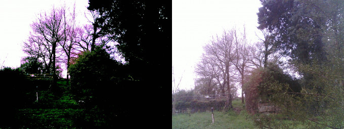
While there may be no observable difference with indoor scenes, outdoor scenes will show problems. Here are two pictures taken with LapseCam. On the left, without any settling delay and on the right with a delay.
Without and with settling delay.
It took me about an hour and a half to write the LapseCam code, and an entire afternoon and the next morning of fiddling in order to get reliable bright-scene working correctly. Indoor scenes were fine, but bright ones tax the auto-adjustments a little more.
The solution was to set up two buffers to run the camera in continual mode, and give some time for things to settle. You can see this for yourself if you run the CameraWebServer and set up QVGA with a quality of 63 (for speed), stream that, and then turn various settings on and off. Messing with AWB, in particular, takes a while to settle.
So that's essentially what we're doing here - giving the camera time to get its act together.
   // Now wait ten seconds for the AEC to settle
   Serial.println("Waiting ten seconds for AEC to settle.");
   delay(10000);
This works for me, using the older SDK. If you are having problems with a newer one that CAMERA_GRAB_LATEST (above) doesn't fix, you could also try discarding a frame. To do this, insert the following at this point:
   // Discard a frame to get a current one
   camera_fb_t * fb = NULL;
   fb = esp_camera_fb_get();  // get framebuffer
   esp_camera_fb_return(fb);  // release framebuffer
   fb = NULL;                 // reset it
and comment out the camera_fb_t * fb = NULL line just below (as we've already done that). This should fix things, but it's untested as I don't have the updated SDK installed.
Oh, yes, I do love when things are changed in incompatible ways...
Take a picture
   // Take a picture
   Serial.println("Smile! :) Taking picture.");
   camera_fb_t * fb = NULL;
   fb = esp_camera_fb_get();
   if (!fb)
   {
      Serial.println("ERROR: Failed to take picture!");
      ESP.restart(); // what else can we do?
      return;
   }
Check/create subdirectory on the SD card
The file is called "image#####.jpg" where the hashes are a five digit number with leading zeros.
The problem is that it isn't possible to write a load of pictures to the root directory of the SD card. The firmware gets as far as writing picture 168 and then doesn't seem to write any more despite saying in the log that it was doing so. Worse than that, deleting one picture as a test caused all of them to be erased and then only the final picture to be saved.
Actually, I don't think it erased anything, I think it's a simple limitation in how many files can be indexed within a directory and this was messing up, badly.
So, to work around this, the images will be saved into subdirectories named 00000, 00100, 00200, etc with the relevant hundred images within each of them. So image 01234 will be in directory 01200.
   // Create subdirectory if necessary
   sprintf(filename, "/%05d", counter);
   if ( ( filename[4] == '0' ) && ( filename[5] == '0' ) )
      if ( ! fs.exists(filename) )
         fs.mkdir(filename); // make the subdirectory if it doesn't exist
Saving the file
Now build up the filename (with path) and attempt to write it to disc.
Once the file has been saved, the counter is incremented and then written to EEPROM for next time.
   // Make a filename
   sprintf(filename, "/%05d/image%05d.jpg", counter, counter);
   filename[4] = '0'; // grotty but
   filename[5] = '0'; // quick ;)
   Serial.printf("Writing picture as \"%s\".\n", filename);

   File file = fs.open(filename, FILE_WRITE);
   if ( !file )
   {
      Serial.println("ERROR: Failed to open file for writing.");
      ESP.restart();
      // ##TODO## Trap if this is because the media is full!
   }
   else
   {
      file.write(fb->buf, fb->len); // buffer data, buffer length
      file.close();

      Serial.printf("Saved %d bytes, updating counter.\n", fb->len);
      counter++;
      EEPROM.write(0,  (counter       & 255));
      EEPROM.write(1, ((counter >> 8) & 255));
      EEPROM.commit();
   }
Tidying up
We can't stop the camera (it seems as if esp_camera_deinit() may crash), but we can free the buffer. A bit pointless as we'll be turning the RAM off, but it's good karma.
The SD card is then forcibly dismounted, and then we force the flash LED to be off. This is the usual case, but it seems that - unlike the red notification LED - the flash LED may be in an indeterminate state when the ESP32 powers down, so it's forced off, and the RTC is instructed to keep it off.
   // Tidy up
   esp_camera_fb_return(fb);
   SD_MMC.end();

   // Turn off the flash LED and force it off
   pinMode(FLASHLIGHT_PIN, OUTPUT);
   digitalWrite(FLASHLIGHT_PIN, LOW);
   rtc_gpio_hold_en(GPIO_NUM_4);
Going into deep sleep
Here the RTC is set up to prod us after sixty seconds have elapsed. Right at the beginning we set ticks to the value of the internal timer. We'll subtract that from the current value so we know how long we have taken.
Then we'll subtract that from sixty million (a minute in microseconds) so we how how long we have to go until the next minute.
There will be a discrepancy of the time it takes to perform the calculation, to set up the RTC, and how far into boot the firmware gets before the timer is initialised. But we're looking at (rough guess) a couple of hundred microseconds. There are a million microseconds in a second, so the drift is not likely to amount to much in the grand scheme of things.
A final message is sent to the serial port, with a short delay and buffer flush to ensure it was sent and that there's no left-over data to worry about.
The red notification LED is then turned off, and finally the ESP32 shuts down as it goes into deep sleep mode.
It's not possible to get an idea of the actual consumption of the ESP32 as active mode (with radios) can consume up to ~260mA (or half that if the WiFi AP is close), while modem sleep (radios off) runs more like 20mA. But... modem sleep also disables peripherals. It seems that the ESP32 can aggressively power down things it isn't using and since I'm not using the radios these ought to be off. So maybe something in the ballpark of 80-90mA? Add to this, around 40mA for the camera when actively taking and compressing a UXGA image.
Deep sleep, on the other hand, keeps only the RTC running (the ULP coprocessor isn't needed for this), so current draw is quoted at around 10µA (or 0.01mA).
There may be some additional loss due to leakage from GPIOs pulled high and the PSRAM being powered, etc.
So what I'll say is that deep sleep mode should consume a lot less than fully active. You can check this for yourself. Run LapseCam and CameraWebServer side by side for an hour. The active server will be warm to the touch, while LapseCam will be cold.
   // Tell the RTC timer to prod us in a minute
   ticks = esp_timer_get_time() - ticks; // our elapsed time
   ticks = 60000000 - ticks; // how much remains of a minute
   esp_sleep_enable_timer_wakeup(ticks);

   // Final status
   Serial.println("Going into deep sleep for a minute, seeya!");
   delay(500);
   Serial.flush();

   // Now turn off the status LED as we're done
   pinMode(LED_PIN, OUTPUT);
   digitalWrite(LED_PIN, LED_OFF);

   // Now do it.
   esp_deep_sleep_start();

   // we never come here
}
And also...
This is a part of the SDK, but in this application, it isn't used.
void loop()
{
   // isn't used
}
Building
This project builds in the Arduino IDE using version 1.0.4, as that's the one that I have running on my PC. Unfortunately it seems as if the v2.x.x versions come with 64 bit tools which aren't going to work on and old 32 bit XP box.
It's all fairly generic, so there shouldn't be any particular issues with any of this code.
Set your device to be an AI Thinker ESP32-Cam board (4MB PSRAM). The code is small, so it shouldn't matter what memory model you choose. I think the usual for these cameras is the "huge app" (3MB + 1MB SPIFFS) memory option. In my Adruino IDE there are no choices, everything is set up automatically when I select the AI Thinker ESP32-Cam board.
DO NOT BUILD using Arduino Studio on Android. It will build (tested using ESP32 SDK 1.0.6), but there's some sort of oddity that will result in only the top quarter (or so) of images being retrieved from the camera.
This was using Arduino Studio 1.4.0(75) 25th June 2022, which is at time of writing the latest release. It's a shame, as it's faster than my PC!
Here is the source. Unpack it into your sketchbook and build it.
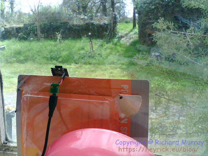
Here is my LapseCam up against the window, photo taken by one of the other ESP32-Cams running my modified CameraWebServer firmware.
LapseCam in place - ESP32-Cam picture.
What it is looking at isn't that impressive. It might have been better to look, say, down the driveway or something. But given the wind and erratic rain, we're just going to have to make do with this. It's a first test, anyway.
LapseCam in place - a better picture.
Serial dump
Each boot, each minute, you'll see something like this.
ets Jul 29 2019 12:21:46

rst:0x5 (DEEPSLEEP_RESET),boot:0x13 (SPI_FAST_FLASH_BOOT)
configsip: 0, SPIWP:0xee
clk_drv:0x00,q_drv:0x00,d_drv:0x00,cs0_drv:0x00,hd_drv:0x00,wp_drv:0x00
mode:DIO, clock div:1
load:0x3fff0018,len:4
load:0x3fff001c,len:1216
ho 0 tail 12 room 4
load:0x40078000,len:9720
ho 0 tail 12 room 4
load:0x40080400,len:6352
entry 0x400806b8

Rick's LapseCam starting.
This is boot 3 since powered up.
Starting camera.
Counter for this image is 3.
Starting SD card.
SD card: capacity 120MB, free 117MB
Waiting five seconds for AEC etc to settle.
Smile! :) Taking picture.
Writing picture as "/00000/image00003.jpg".
Saved 485193 bytes, updating counter.
Going into deep sleep for the rest of this minute, seeya!
Enhancements
It is not possible to burn a date/time into the picture. This is because the image is returned a JPEG data and thus the individual pixels are not accessible. You may be able to retrieve a VGA (640×480) image in RGB565 (16 bit; 614,400 bytes) to fiddle around with, but really sizes above CIF may run into timeout errors when transferring the data to buffer. Technically, RGB565 at SVGA would fit into the larger buffer (it's exactly 960,000 bytes) but the camera will timeout with that.
As for smaller image sizes, look at the CameraWebServer example code, it draws stuff into the image in order to mark detected faces. You could use a similar method to write the data and time into the image. But, then, is it worth it given you'd be shrinking the image to two fifths of it's maximum resolution?
It could be possible to have a text file with a name like "config.txt" that contains settings such as:
delay=15
framesize=9
quality=10
which you can parse and use to control the camera behaviour.
More complicated, if disc space is running low (probably not an issue for you, I'm using the 128MB (!) card that was supplied with my camera) look for and delete one with the lowest number (repeat until there is enough space).
And so on. Happy coding!
Your comments:
Please note that while I check this page every so often, I am not able to control what users write; therefore I disclaim all liability for unpleasant and/or infringing and/or defamatory material. Undesired content will be removed as soon as it is noticed. By leaving a comment, you agree not to post material that is illegal or in bad taste, and you should be aware that the time and your IP address are both recorded, should it be necessary to find out who you are. Oh, and don't bother trying to inline HTML. I'm not that stupid! ☺ ADDING COMMENTS DOES NOT WORK IF READING TRANSLATED VERSIONS.
You can now follow comment additions with the comment RSS feed. This is distinct from the b.log RSS feed, so you can subscribe to one or both as you wish.
David Pilling, 1st April 2023, 13:19
Shows what a big enough community can do as regards making things easy to use. Oddly enough I was an early adopter, over seven years since my first (and last) ESP8266 project, and back then Espressif made it difficult. I lost interest, why mess about with something that is poorly documented when you're only doing it for fun.
I set out to do a time lapse camera with Pi Zero, spent too long on the solar power side and never finished it.
This web page is licenced for your personal, private, non-commercial use only. No automated processing by advertising systems is permitted.
RIPA notice: No consent is given for interception of page transmission.