It is the 1727th of March 2020 (aka the 21st of November 2024)
You are 18.227.114.218,
pleased to meet you!
mailto:blog-at-heyrick-dot-eu
Hacking the Aixam remote door lock
I have two remote locks for my Aixam GTO. The first is a broken one that is built into the key itself (a broken switch). The replacement is a little dongle thing that I use instead.
As part of looking at what was wrong with the key fob controller, I popped a CR2032 cell into it and noticed that the little blue LED blinked rapidly when I pressed the working key or shorted across the broken key with a small screwdriver.
I noticed, especially, that the LED was not 'on' nor was it blinking. It was flickering. Flickering in a manner that suggested to me that it was wired in series with the antenna. So what I was seeing was the actual data stream being transmitted.
Let's back up a little and look at what we actually have here:
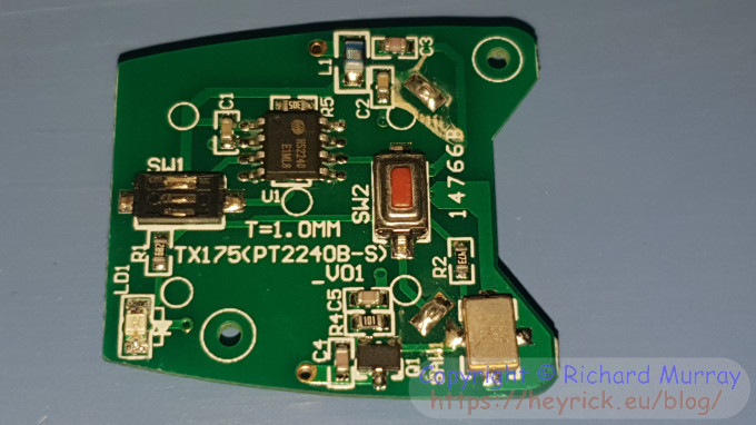
Key fob circuit.
The silver blob at the lower right is a 433MHz sawtooth generator (a clone of the R860) that is nomimally outputting pulses at 433.920MHz. This provides the master timing of the keyfob.
There are two switches, the red one (working - unlock) which is wired as input K2, and the broken one (centre left - lock) which is wired as input K3.
Inputs K0 and K1 are unconnected, they are internally pulled down so would read as a zero.
The little chip is an HS2240. This accepts the 433MHz signal and chops it to output a sequence of pulses that are to be transmitted. These pulses will represent digital zero and digital one, to transmit a fob ID and the status of the key inputs.
How it transmits is some of the rest of the circuit - a simple AM radio transmitter based at the 433.920 MHz frequency, with the bitstream overlaid on top.
That it is using the HS2240 is not good. This cheap little piece of crap is used in basic low budget garage door openers. The problem is that the signal that it outputs is always the same. There is no crypto, there is no scrambling with some sort of sequence known to the car. Nothing. Every time you press the unlock key, it outputs exactly the same sequence.
This sequence can easily be captured by an Arduino wired to a 433MHz receiver board. Once you've captured the bitstream, replay it and the car will unlock.
Pretty much the only 'security' is... well, let's face it, Aixam cars are not known for being in any way secure owing to their plastic bodywork, and everything being glued into place. I've not tried as I don't want to damage my car, but I reckon I could get inside in about ten seconds (wedge a large flat-bladed screwdriver under one of the back windows, prise it away from the body, reach in, unlock the door). So the key fob being equally lame is... not really a surprise.
The replacement key fob I have has three buttons, the third one is for unlocking the boot hatch. This doesn't work on my car as it is older and the boot is manual. However it suggests that more recent Aixams have the same key fob hardware.
Oh, and since this is Rick's b.log, you know we aren't just going to say "lame ass crap" and call it quits.
Let's dive deeper.
Ready?
I was right in thinking that the pulsing of the LED was the bitstream that was transmitted. Very convenient to hook my oscilloscope across the terminals of the LED and set it to single trigger mode to capture a snapshot of the waveform.
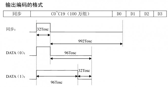
Before we do that, here is the data transmission from a TDK HS2240 datasheet.
Transmission protocol.
What is described here isn't what is overly complicated, because different resistance values and input voltages allow the timing to be adjusted. It's a bit of a pain in the ass to read, though. So along the way we'll simplify it.
According to the datasheet, the transmission begins with a sync pulse which is 32 oscillations, and a space of 992 oscillations following. Don't worry too much about what this actually means. Just know it isn't a 433MHz tick, because that is 0.0023 microseconds (and 32 of them would be 0.0737 microseconds). 433MHz is our carrier frequency, the on and off timings that we see are actually dramatically longer.
By observing the waveform things really do become a lot simpler. So, let's do that...
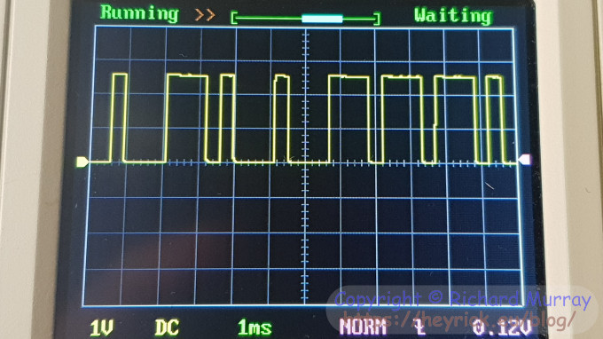
Working out the pulse timing.
With the oscilloscope set to 1 millisecond, we can start to get an idea of what is going on here.
The protocol data suggests that a '1' is 96 oscillations followed by a space of 32, while for a '0' it is 32 oscillations followed by a space of 96.
If we can reduce that into something legible to normal people, that's one period on and three periods off for a '0'; with three on and one off for a '1'.
Forthwith, the on periods will be called pulses, and the off periods will be called spaces.
But how long is a period? Looking at the above photo, the pattern is actually quite clear. Each digit (0 or 1) last for four 'periods', and a period is about 0.3 milliseconds (or ~300 microseconds), with an entire digit being about 1.2 milliseconds.
A zero is one pulse (0.3ms) followed by three spaces (0.9ms).
A one is three pulses (0.9ms) followed by one space (0.3ms).
As you can see, the timing is a little sloppy. The datasheet suggests to allow for a deviation of up to 20%.
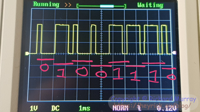
Don't get hung up on the pulses and spaces. Just read it as "short pulse is a zero" and "longer pulse is a one" and ignore the spaces. ☺
This should make it clearer.
Decoding the timing.
The protocol starts with a single pulse. My oscilloscope doesn't capture this, but it one would assume that it's a single 0.3 millisecond pulse.
There follow twenty squares of nothing at 2ms resolution (need to switch to 2ms to capture the entire waveform). That's 40 milliseconds, which would be a whopping 133 spaces. The datasheet implies a pulse followed by 30 spaces of nothing. Given 30 spaces would fit the screen, I'm not sure why the initial gap is so large.
Following this, the zeros and ones as described above.
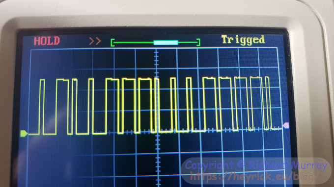
So let's look at a complete waveform.
Waveform, first half.
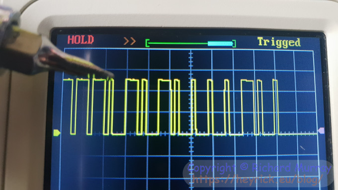
Waveform, second half.
The screwdriver in the second half indicates the start of a zero that appears at the right of the first half.
Looking at the images, it looks to me like the unlock code is 010011100011110 (from the first half) and 1010000100 from the second half. 0100 1110 0011 1101 0100 0010 0 in total.
I have spaced it out with the trailing zero, as I think this is actually supposed to be a sync pulse for the following (shorter) gap before the sequence repeats. The gap here seems to be about 30(ish) spaces, so that would match up with the documentation. It's just the initial sync gap that is massive.
If we were to push the lock key (wired to K3), the sequence would become: 0100 1110 0011 1101 0100 0001 0
If you didn't catch that, the final group of four appears to represent the keys, with K2 (unlock) setting the third '1' and K3 (lock) setting the fourth '1'.
I would go out on a limb here and guess that the boot unlock is probably going to be: 0100 1110 0011 1101 0100 0100 0
So there are five nibbles of a code unique to this key fob. Five nibbles is &FFFFF or 1,048,575 unique codes. As a quick aside, you might see from the protocol description in Chinese that it says "100万". This is because in Chinese (and Japanese), there is no ordinal number for "million". The character 万 means ten thousand, so it is literally "a hundred ten thousands".
Well... it's not so different to four-twenties-ten-seven which is how you say 97 in French!
Following this is a final nibble that represents whether or not the four key inputs are active. Which bit is set indicates which key has been pressed.
I just shorted K1 and K2 and pressed unlock (K2) and the button codes were 0110 which would indeed correspond with the second and third buttons having been pressed.
If this key fob worked on my car, simply getting an Arduino to spit out a pulse followed by a gap, and then 0100 1110 0011 1101 0100 0010 0 and... you'd unlock my car.
Secure, huh? ☺
Your comments:
Please note that while I check this page every so often, I am not able to control what users write; therefore I disclaim all liability for unpleasant and/or infringing and/or defamatory material. Undesired content will be removed as soon as it is noticed. By leaving a comment, you agree not to post material that is illegal or in bad taste, and you should be aware that the time and your IP address are both recorded, should it be necessary to find out who you are. Oh, and don't bother trying to inline HTML. I'm not that stupid! ☺ ADDING COMMENTS DOES NOT WORK IF READING TRANSLATED VERSIONS.
You can now follow comment additions with the comment RSS feed. This is distinct from the b.log RSS feed, so you can subscribe to one or both as you wish.
David Pilling, 22nd June 2021, 23:22
"433MHz sawtooth generator" - SAW == surface acoustic wave Very interesting. I'd imagine the lowly processor is plodding along at some low frequency and making the SAW produce bursts of 433MHz radiation. Q1 is likely a transistor the CPU uses to switch power to the SAW.
David Pilling, 23rd June 2021, 01:42
... the SAW is just a resonator, like a crystal, so Q1 may be an amplifier that generates oscillations at the SAW frequency.
This web page is licenced for your personal, private, non-commercial use only. No automated processing by advertising systems is permitted.
RIPA notice: No consent is given for interception of page transmission.